Mesh
Quanscient Allsolve mesh configuration is done in the Simulations section. You can easily manage multiple meshes within your project for simulations. Each simulation can have its own dedicated mesh, or you can choose to share a common mesh between simulations.
Mesh quality
After creating a mesh, you can select the quality from predefined settings or configure the mesh settings manually for more control.
- Coarse
- Uses mesh refiner with scale factor of 0.5
- Default
- Uses mesh refiner with scale factor of 1
- Fine
- Uses mesh refiner with scale factor of 2
- Expert settings
- Configure all settings manually
Expert settings
With the expert settings all meshing parameters are tunable.
Mesher
Basic
Has no intelligent refinement but in some cases produces a more uniform mesh. If mesh refiner mode fails, you can try this option.
Mesh refiner (default)
Mesh refiner refines the mesh automatically.
- Automatically creates a finer mesh around steep curves
- Retrying with a finer mesh if meshing fails because of bad mesh outputs like too elongated tetrahedra.
Size
Min size and max size set the absolute minimum and maximum size of mesh elements in mesh. If the values are not set, the resulting sizes are decided by the mesher algorithm.
Scale factor
Once the initial round of meshing succeeds, the mesh can be scaled down or up. Value of 1 will keep the mesh size at the initial value, 0.5 would scale the mesh size down to 50% and a value of 2 would make mesh elements twice the size.
The scaling is applied after all other sizing, excluding structured and extrude meshing.
Curvature enchancement
If the geometry has rounded edges, you can fine tune the curvature enhancement. The value determines how many elements are used to represent a full circle. For instance, a value of 12 would force at least 3 elements to be used for a 90-degree corner.
Curved mesh
Sets the mesh order to 2 effectively using 2nd order elements for curved surfaces.
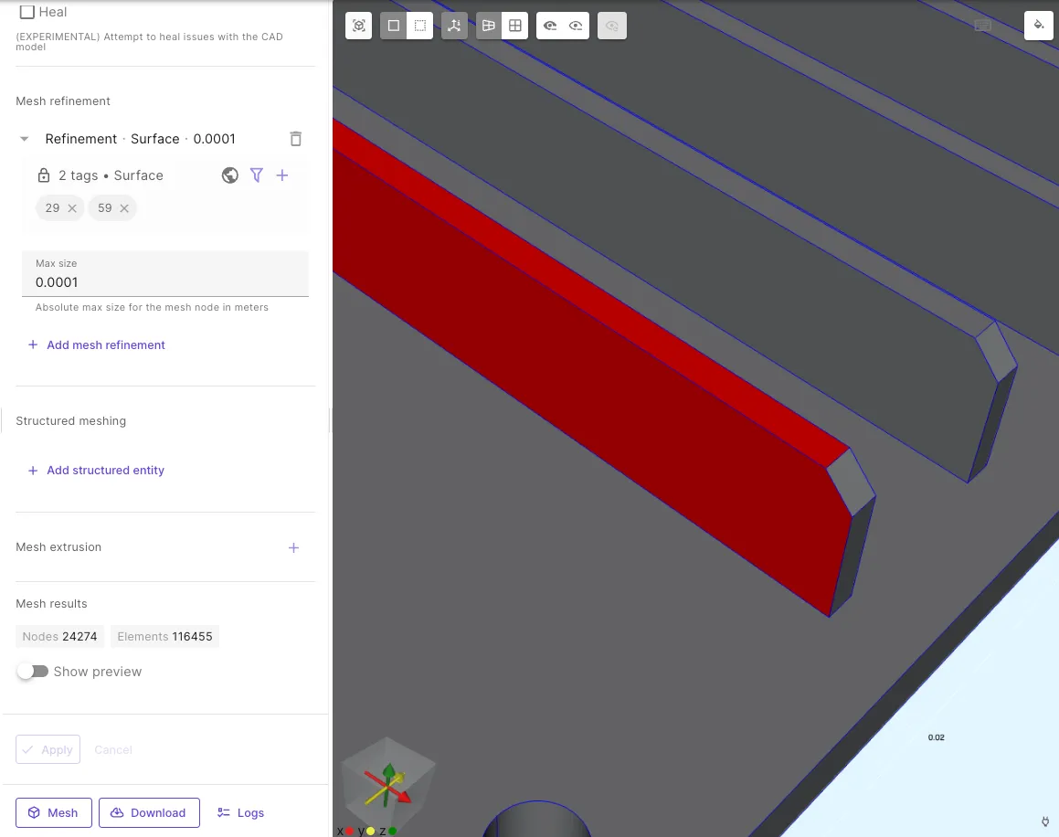
Mesh refinement
Mesh refinement allows setting absolute sizes of elements for specific geometry elements. Mesh refinement can target volumes, surfaces or curves. Once the target type is selected, fill in the refinement value in meters. Any number of refinements can be added.
| Mesh refinement target | Meshing results |
|---|---|
 | 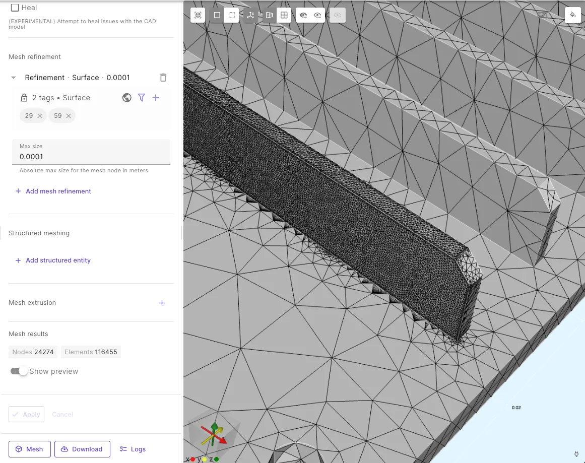 |
Structured meshing
Structured meshing allows configuring certain elements to use hexahedral mesh elements (quadrilateral in 2D).
Boundaries of hexahedral and tetrahedral mesh volumes will be meshed using pyramids.
- Choose the target entity (surface, volume or curve) you want to set.
- Input values for each dimension of your selection. (For volume target, you will input three curve segment counts and two for surfaces). As you hover over a curve label (A/B/C), the corresponding curve in the model view will be highlighted.
- The application calculates an average mesh element size based on your inputs. Aim to keep the resulting lengths of each curve within a range of 1/3 to 3 times any other curve length for optimal results.
| Structured mesh target | Meshing results |
|---|---|
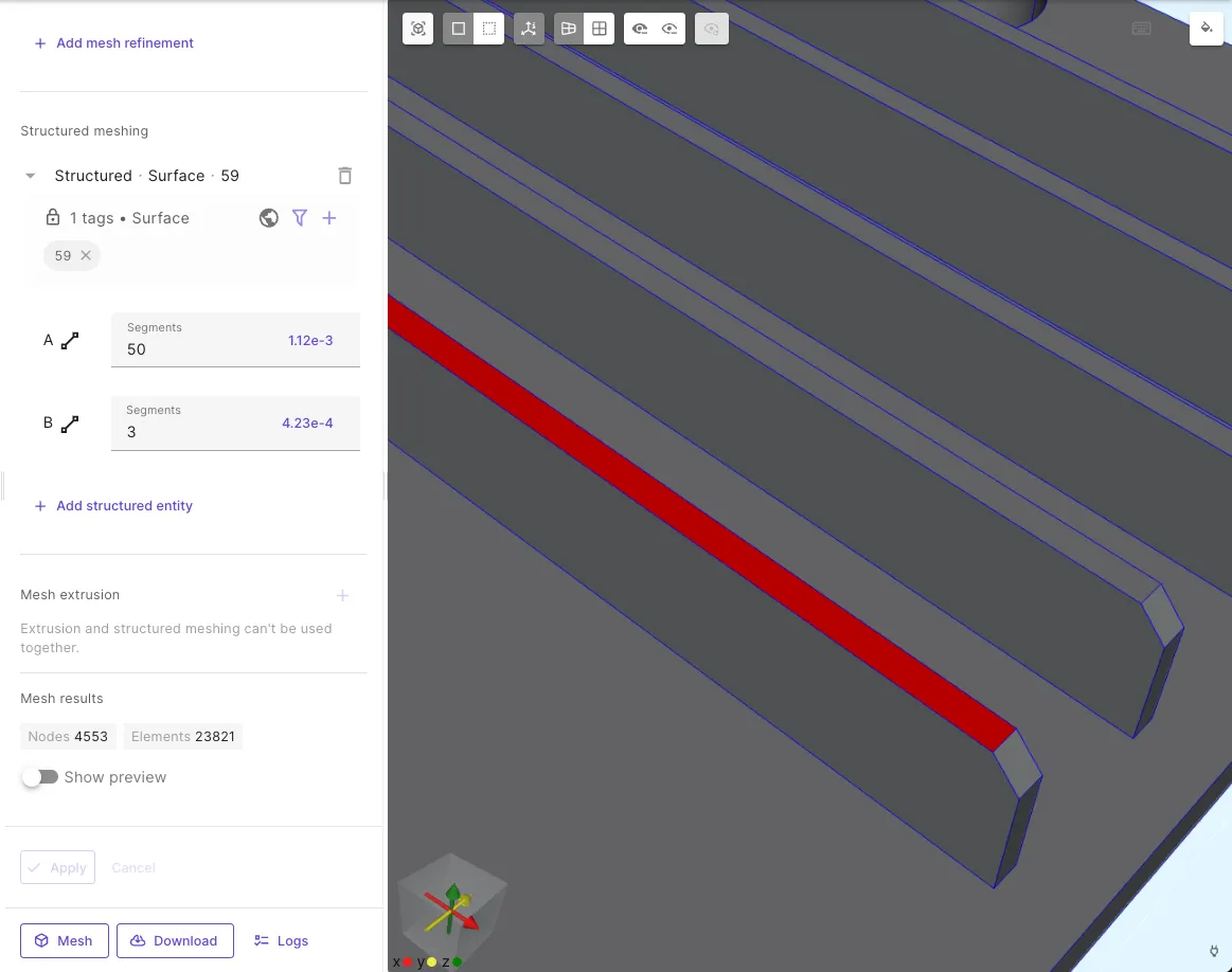 | 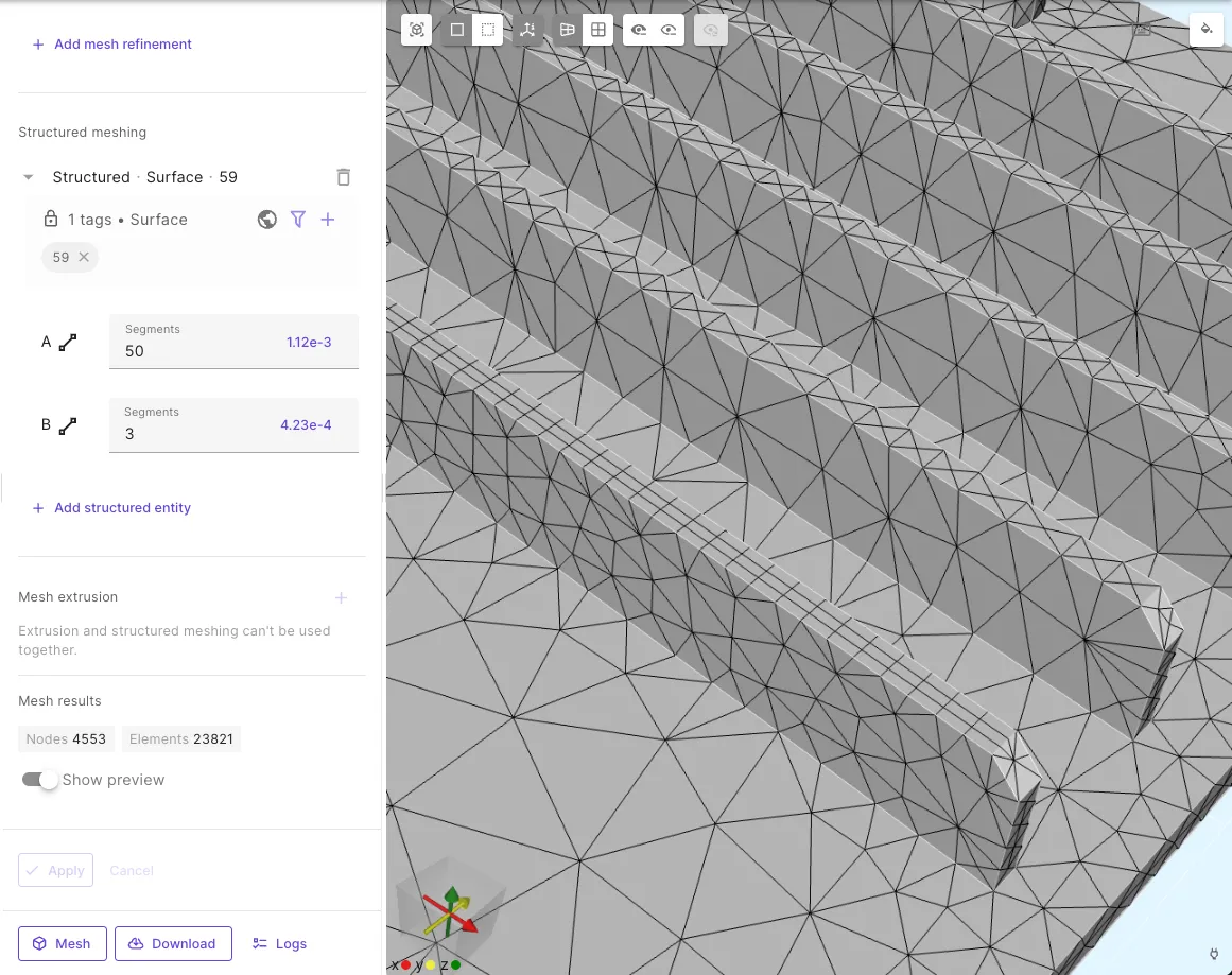 |
Mesh extrusion
Mesh extrusion is a meshing technique which extrudes a 2D planar mesh by the specified number of layers in the plane’s perpendicular direction to create a 3D mesh. The target volume of mesh extrusion will consist of prism elements. Extruded mesh offers control and efficiency, especially with thin or geometrically regular structures.
Benefits of Extruded Meshes
- Optimized for thin planes: Extruded meshes excel at modeling thin planar structures, minimizing element count while maintaining accuracy.
- Control over mesh density: Adjust the number of layers within an extrusion to precisely control mesh resolution.
- Enhanced mesh quality: Extrusion often leads to more regular, high-quality meshes with fewer poorly shaped elements compared to tetrahedral or hexahedral volume meshing technique.
Limitations
- Geometry restrictions: Suitable geometries must have at least two surfaces parallel to the XY-plane at different Z-levels. All other surfaces and curves must be perpendicular to it XY-plane. Curved edges are allowed only on the XY-plane.
- Z-axis extrusion only: All extrusions occur in the positive Z-axis direction.
- Layer consistency across shared Z-coordinates: For extruded volumes to merge correctly, they must have identical layer sizes in the areas where they have matching Z coordinates.
- No mixed meshing: Volumes using mesh extrusion cannot be combined with structured meshing volumes in the same mesh.
- No extrusions touching by a curve: The boundary of two extruded volumes cannot share only a curve. The volumes must either be completely separate or they must have a shared surface at the boundary.
- Potential boundary issues:
- Complex non-extruded boundaries or very thin (relative to the area of the extruded volume) interfacing volumes can lead to meshing failures.
- Non-extruded volume sharing a side boundary (in z-direction) with one or more extruded volumes must always share the full height of the side boundary with one or more extruded volumes. Meshing will likely fail if the non-extruded volume only shares a part of the side boundary height with an extruded volume.
- Internal splitting: Extrusion typically splits the geometry into new surfaces and volumes to make the boundary between volumes match. These entities are automatically mapped by the generated code to the original geometric entities. If you wish to download the mesh and use it elsewhere, you need to do this mapping yourself. For custom scripts, see the automatically generated scripts for an example of how to do the mapping.
- Performance impact: Meshing stacked extrusions can be slow if volumes contain many surfaces with curved edges. This will cause internal splitting of volumes and surfaces which takes some additional time.
How to Perform Mesh Extrusion
- Access Expert Mesh Settings: Navigate to your mesh settings and select “Expert” settings.
- Add a Mesh Extrusion: Click the ”+” icon within the “Mesh Extrusion” section.
- Set Overlap Mode:
- Prevent: Fails meshing if a non-extruded volume shares the same Z-coordinate with any of the extruded volume.
- Allow: Allows meshing when a non-exruded volume shares a Z-coordinate with any of the extruded volume. Uses pyramids to transition at extrusion boundaries within non-extruded volumes.
- Select Target Volumes: In the “Target” section, choose the volumes to be extruded. You can define multiple target groups that are not connected to each other.
- Layer Configuration: The number of required layers is determined automatically, but you need to give the number of sublayers for each layer. The sublayer input fields are numbered in ascending Z-coordinate order.
- Apply: Click “Apply” to save your extrusion settings.
- Mesh: Mesh the geometry and mesh extrusion creates prisms within the extruded volumes and pyramids for seamless transitions at the side boundaries with non-extruded volumes. The mapping for the original entity tags to the meshed entity tags is also generated at this phase.
Details
Mesh extrusion for a geometry is explaned here in more detal.
Consider the geometry in Image 1. There is just one volume with 10 surfaces in the geometry.

The extrusion of the geometry in Image 1 results in 3 layers corresponding to the number of XY-plane-aligned surfaces in different Z-coordinate minus 1 (i.e. surfaces 1, 2, 3 and 4 in Image 1). Each layer is extruded separately with the number of sublayers defined in the extrusion settings.
The result of the extrusion is shown in Image 2. There are 6 volumes and 30 surfaces in the resulting extruded mesh geometry because of splitting the volumes and surfaces. After the mesh extrusion, each XY-plane aligned layer boundary surface must exactly match to the boundary surface directly above and below.
In Image 2 we can see that due to this requirement, surface 9 is mapped to six surfaces in the resulting mesh extrusion geometry. Similarly, surface 3 is mapped to two surfaces. Note also that there are three unmapped surfaces in the resulting geometry where there were no surfaces in the original geometry.
Volumes and curves are mapped similarly as the surfaces. Point mapping is a bit different, as a point always maps to a single point. There still needs to be a point mapping, as the point tags in the source geometry and in the resulting extruded mesh geometry may differ.

The volume, curve and point mappings are left out of the Image 2 in order to keep the image easier to read. Surface mapping for original geometry surface 10 is omitted in order to make the image easier to understand.