Permanent Magnets
In this tutorial, the magnetic fields and magnetic forces resulting from a pair of small permanent magnets is simulated.
Model definition
Section titled “Model definition”The model consists of two cylindrical 2 mm permanent magnets separated by a distance of 1.2 mm and an air box surrounding them.
A constant magnetic flux density is applied to the magnets. The resulting magnetic forces are determined with the Magnetism-φ formulation.
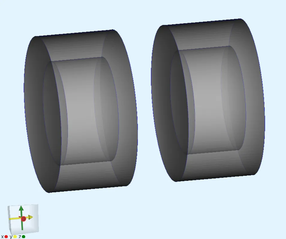
Additional cylindrical force domain volumes are created around the magnets, so that the magnetic fields around the magnets can be integrated.
| Element | Geometric details |
|---|---|
| Magnet 1 | Cylinder of 2 mm radius and 2 mm height centered at |
| Magnet 2 | Cylinder of 2 mm radius and 2 mm height centered at |
| Force domain 1 | Cylinder of 3 mm radius and 3 mm height centered at |
| Force domain 2 | Cylinder of 3 mm radius and 3 mm height centered at |
| Air box | Box of size 50 mm 50 mm 50 mm |
Output Results
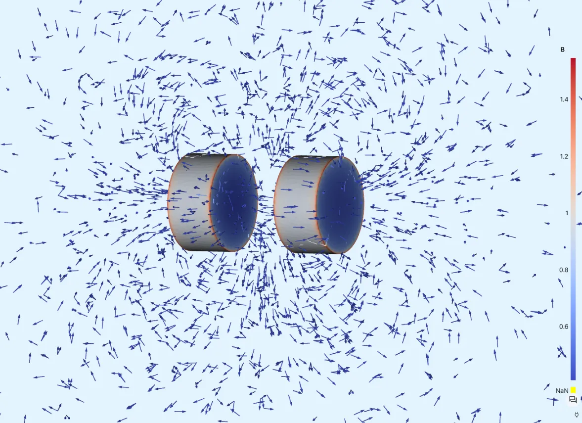
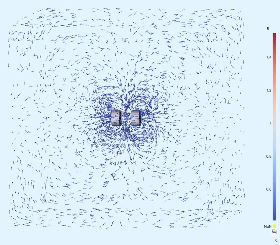
Section titled “Output Results”- Magnetic field distribution.
- Magnetic forces between the magnets.
Material Data
Section titled “Material Data”- Air
| Property | Value |
|---|---|
| Magnetic permeability |
Boundary conditions
Section titled “Boundary conditions”| Type | Value | Target volume |
|---|---|---|
| Remanence | [0, 1.35, 0] | Magnet 1 |
| Remanence | [0,-1.35, 0] | Magnet 2 |
Step-by-step guide
Section titled “Step-by-step guide”Here you’ll find a detailed step-by-step tutorial on how to simulate a pair of permanent magnets and the resulting forces in Quanscient Allsolve.
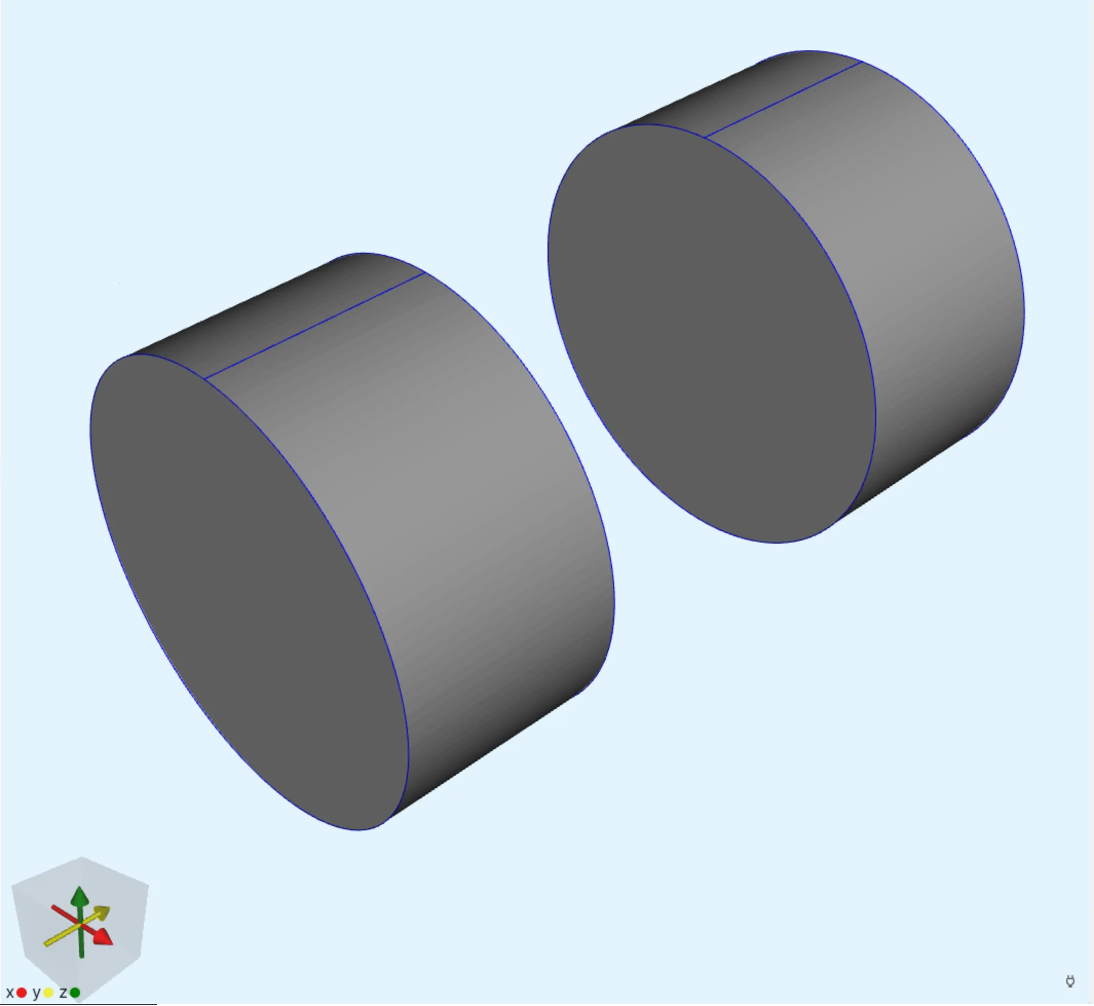
Step 1 - Build the geometry
Section titled “Step 1 - Build the geometry”-
Create a new project and name it
Permanent magnets. -
Start off with a
cylinderelement.Name Element type Center point [m] Size [m] Rotation [deg] magnet 1 Cylinder X: 0Radius: 2e-3X: 0Y: 2.5e-3Height: 2e-3Y: 0Z: 0Z: 0Note, that rotation in the X-direction is
0. -
Reset view after building
magnet 1to bring the small magnet cylinder back into view. -
Copy
magnet 1to buildmagnet 2.Name Element type Center point [m] Size [m] Rotation [deg] magnet 2 Cylinder X: 0Radius: 2e-3X: 0Y: -2.5e-3Height: 2e-3Y: 0Z: 0Z: 0 -
Copy
magnet 1to buildforce domain 1.Name Element type Center point [m] Size [m] Rotation [deg] force domain 1 Cylinder X: 0Radius: 3e-3X: 0Y: 2.5e-3Height: 3e-3Y: 0Z: 0Z: 0 -
Copy
force domain 1to buildforce domain 2.Name Element type Center point [m] Size [m] Rotation [deg] force domain 2 Cylinder X: 0Radius: 3e-3X: 0Y: -2.5e-3Height: 3e-3Y: 0Z: 0Z: 0At this point, there are 4 cylinders in the model, so that the force domains envelop the magnets that are facing each other.
-
Build the air box.
Name Element type Center point [m] Size [m] Rotation [deg] box Box X: 0X: 50e-3X: 0Y: 0Y: 50e-3Y: 0Z: 0Z: 50e-3Z: 0
Step 2 - Define materials
Section titled “Step 2 - Define materials”-
Go to the
Physicssection. -
tosign the
Airmaterial to all volumes.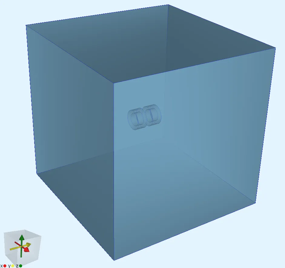
Step 3 - Define the physics and apply boundary conditions
Section titled “Step 3 - Define the physics and apply boundary conditions”-
Add the
Magnetism ϕinteraction. Let the target default to all volumes.Physics Target Magnetism φ All volumes -
Add a
Remanenceinteraction to Magnetism φ. Remanence introduces a B-field to a volume.Interaction name Interaction type Target Value Remanence left Remanencemagnet 2 (volume 4)[0; 1.35; 0]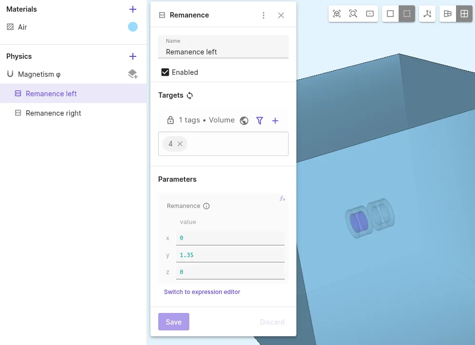
-
Add another
Remanenceinteraction to Magnetism φ.Interaction name Interaction type Target Value Remanence right Remanencemagnet 1 (volume 1)[0; -1.35; 0]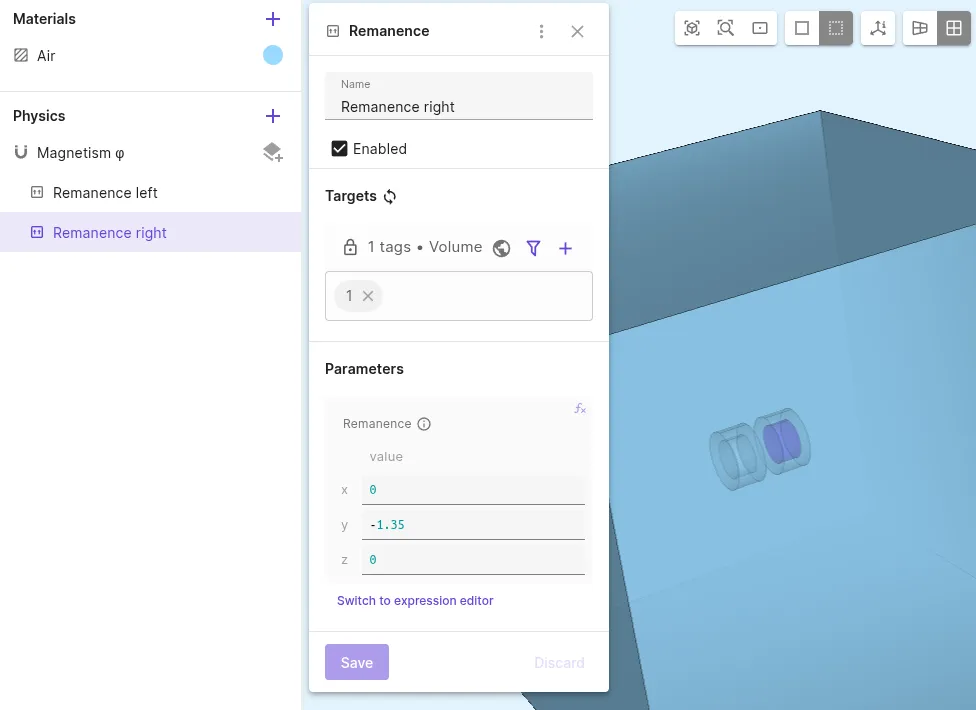
Step 4 - Generate the mesh
Section titled “Step 4 - Generate the mesh”-
Go to the
Simulationssection. -
Create a new mesh.
-
Set Mesh quality to
Expert Settings. -
Set the mesh element Max size to
0.05. -
Scroll down to Mesh Refinement and create a
Volumemesh refinement entity. -
Select all cylindrical volumes to target and set Max size to
0.0001.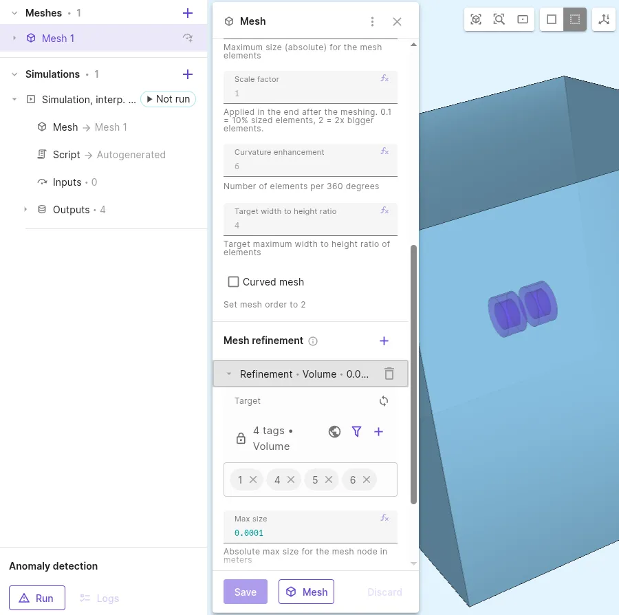
-
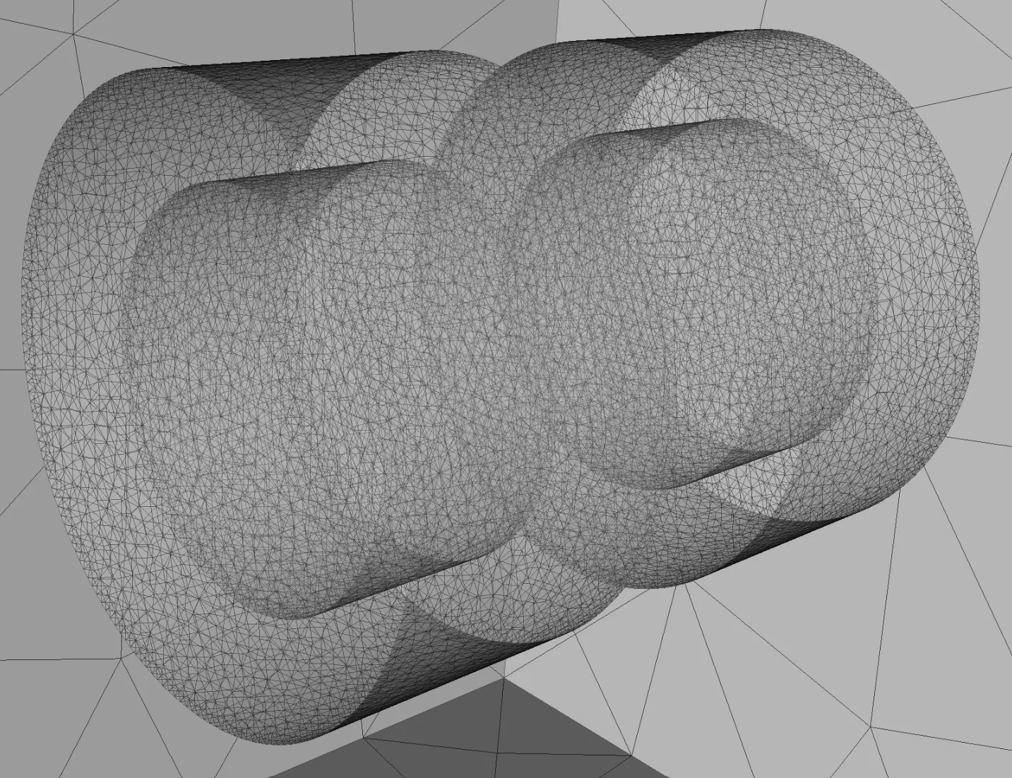
Generate the mesh and check the preview.
Step 5 - Apply simulation settings
Section titled “Step 5 - Apply simulation settings”-
Create a new simulation.
Simulation name Analysis type Node count Node type Simulation 1 Static 51 CPU, 16 GB -
Select
Mesh 1as the mesh for your simulation. -
Add a
Bfield output.Output name Output type Target Output expression B magnets Magnetic flux density ( B) field outputmagnets 1 and 2 (volumes 1, 4)B -
Add another
Bfield output.Output name Output type Target Output expression B air Magnetic flux density ( B) field outputForce domains 1 and 2, air box (volumes 5, 6, 7)B -
Add a
Magnetic forcevalue output.Output name Output type Target Magnetic force left Magnetic force value output magnet 2 and force domain 2 (volumes 4, 6) -
Add another
Magnetic forcevalue output.Output name Output type Target Magnetic force right Magnetic force value output magnet 1 and force domain 1 (volumes 1, 5) -
Run the simulation.
Step 6 - See results
Section titled “Step 6 - See results”-
Check
Summaryfor the magnetic force value outputs.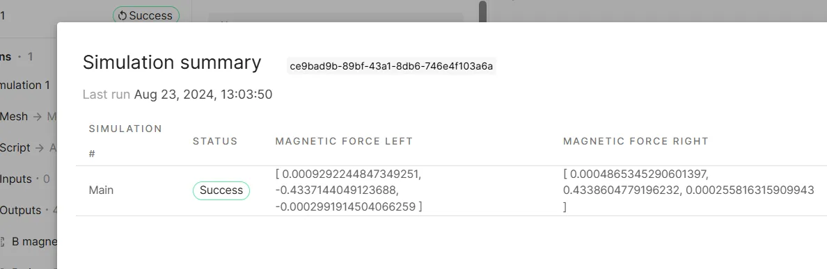
-
Add a visualization to see field output results:
Visualization name Fields Filters Visualization 1 B magnets B air Glyph -
Edit the
Glyphsettings:Filter Max sample points Scale factor Glyph 500000.001 -
Render the visualization.
-
The
Glyphscale factor is reduced to0.0005here for a closer look: