HB 003 - MEMS Microspeaker
Electrostatically actuated silicon-based microspeakers are an emerging technology due to their obvious advantages, providing high sound quality over a wide range of frequencies 1 2.
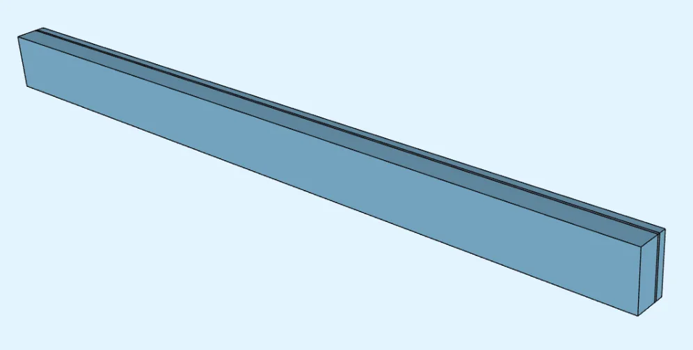
Multiharmonic analysis is conducted for a MEMS microspeaker in this example using a harmonic balance method.
Demo project: mems-microspeakers-webinar. The demo was presented in a Quanscient webinar 3.
Simulation setup guide
Section titled “Simulation setup guide”Below, you’ll find a simplified guide for setting up a multiharmonic analysis simulation for a MEMS microspeaker in Quanscient Allsolve.
Step 1 - Define variables
Section titled “Step 1 - Define variables”Start out in the Common sidebar by defining the following variables:
| Name | Description | Expression |
|---|---|---|
| L | Length [m] | 1000e-6 |
| W | Width [m] | 75e-6 |
| T | Thickness [m] | 3e-6 |
| g0 | Initial gap [m] | 10e-6 |
| freq | Frequency [Hz] | 100 |
| Voltage | Voltage [V] | 30 |
Step 2 - Create the geometry
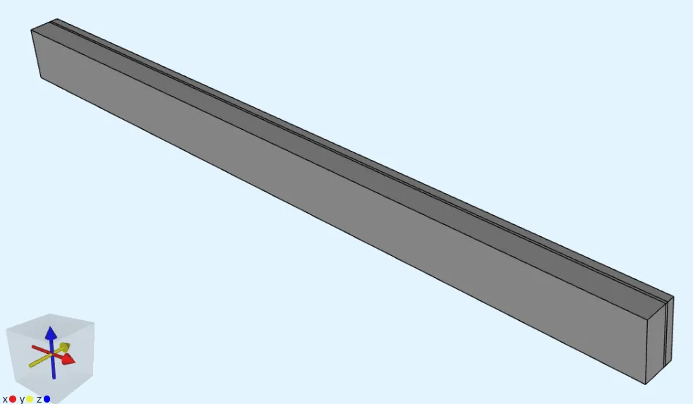
Section titled “Step 2 - Create the geometry”In the Model section, create the model geometry by creating Box elements as follows.
-
Create the first box:
Name Element type Center point (m) Size (m) Rotation (deg) box Box X: 0X: LX: 0Y: 0Y: TY: 0Z: 0Z: WZ: 0 -
Create the second box by copying the first one, and editing
Center point YandSize Yparameters:Name Element type Center point (m) Size (m) Rotation (deg) box 2 Box X: 0X: LX: 0Y: T/2 + g0/2Y: g0Y: 0Z: 0Z: WZ: 0 -
Create the third box by copying the second one, and editing
Center point YandSize Yparameters:Name Element type Center point (m) Size (m) Rotation (deg) box 2 2 Box X: 0X: LX: 0Y: -T/2 - g0*1.5Y: 3*g0Y: 0Z: 0Z: WZ: 0
Finished geometry:
Step 3 - Define the materials
Section titled “Step 3 - Define the materials”Go to the Physics section.
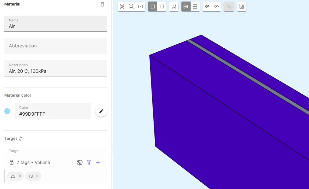
Material 1 - Air
Section titled “Material 1 - Air”- Assign
Airto the 2 outer box volumes (13, 25). - Share the target region.
- Save the material settings.
Material 2 - Monocrystalline silicon
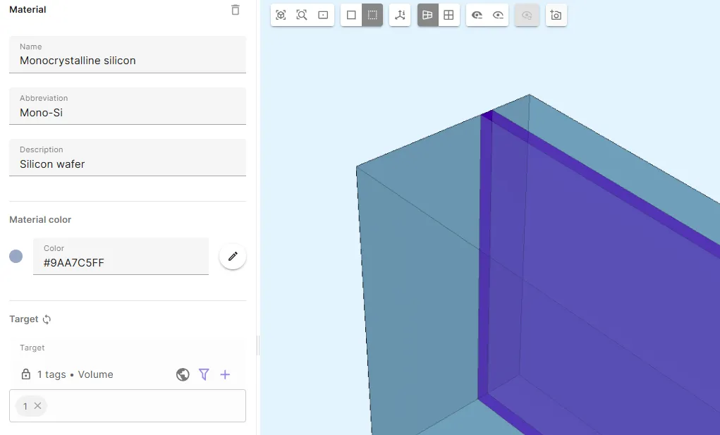
Section titled “Material 2 - Monocrystalline silicon”- Assign
Monocrystalline siliconto the intermediate box volume (1). - Share the target region.
- Save the material settings.
Step 4 - Define the physics
Section titled “Step 4 - Define the physics”Go to the Physics section.
In this example, Solid mechanics, Electrostatics, Laminar flow and Mesh deformation physics are required. Add all of them before moving on to define interactions.
Physics 1 - Solid mechanics
Section titled “Physics 1 - Solid mechanics”- As solid mechanics target, select the
Monocrystalline siliconregion. - Add
Clamp.- As Target, select the outer edge surfaces of the silicon volume in the positive-X and negative-X ends.
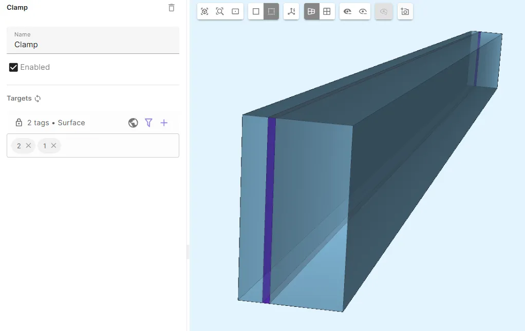
- Add the Solid mechanics - Mesh deformation coupling
Large displacement. - Add the Solid mechanics - Electrostatics coupling
Electric force. - Add
Geometric nonlinearity.
Physics 2 - Electrostatics
Section titled “Physics 2 - Electrostatics”- Let electrostatics target default to the whole geometry.
- Add
Constraint.- As Target, select the
Monocrystalline siliconregion. - Set Constraint value to
Voltage*sin(2*pi*0.5*freq*t). 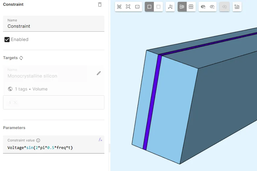
- As Target, select the
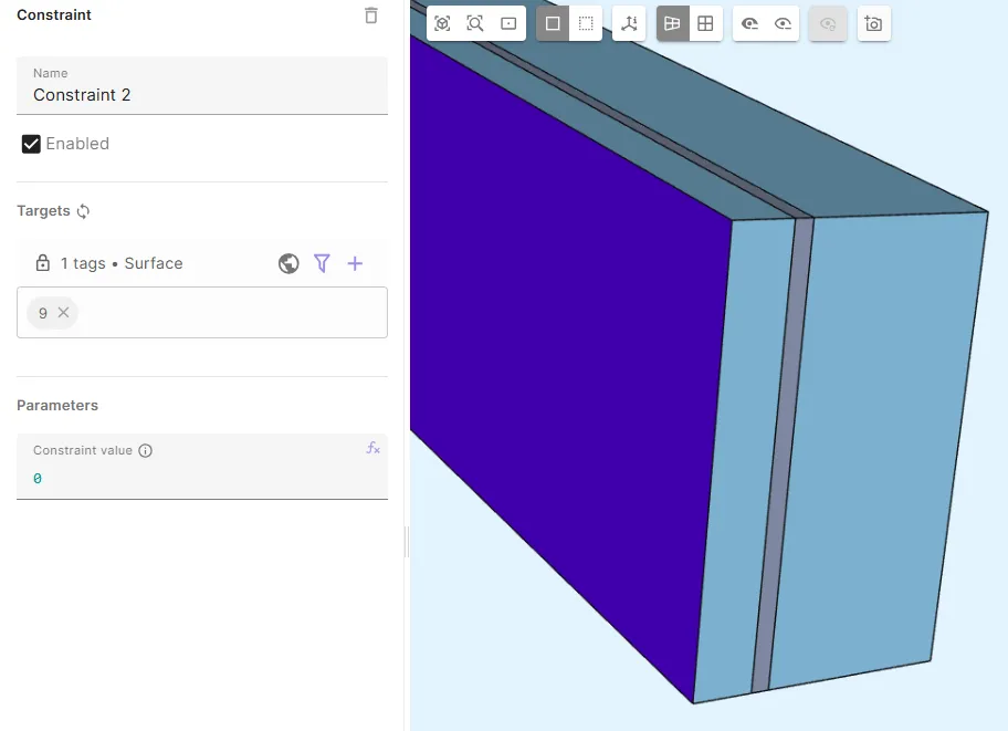
- Add
Constraint 2.- As Target, select the air box surface
9. - Set Constraint value to
0. 
- As Target, select the air box surface
- Add the Electrostatics - Mesh deformation coupling
Large displacement.
Physics 3 - Laminar flow
Section titled “Physics 3 - Laminar flow”- As laminar flow target, select the
Airregion. - Add
Velocity constraintand name it asnoslip.- As Target, select surfaces
7 - 10, 12, 13, 15, 16. - Set Constraint value to
[1, 0; 1, 0; 1, 0]. 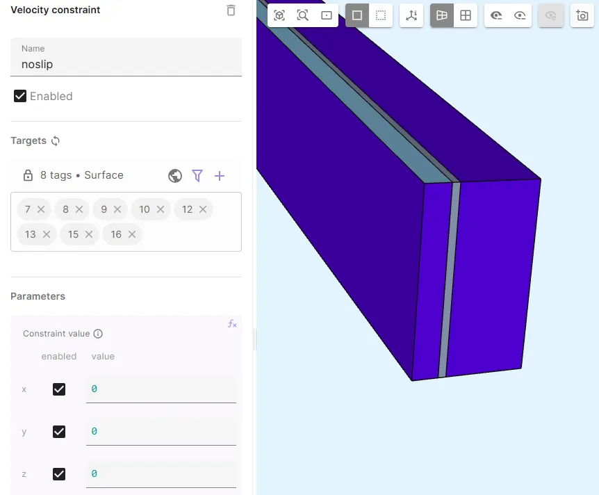
- As Target, select surfaces
- Add
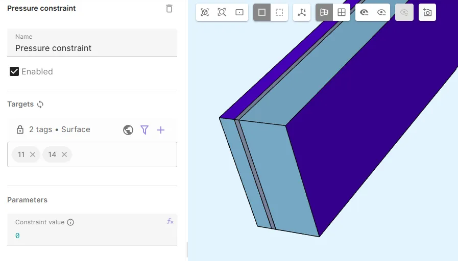
Pressure constraint.- As Target, select the air box surfaces that were not included in
nosliptarget (11, 14). - Set Constraint value to
0. 
- As Target, select the air box surfaces that were not included in
- Add the Laminar flow - Solid mechanics coupling
Fluid structure.- As Target, select the silicon and air interface surfaces (
3, 4).
- As Target, select the silicon and air interface surfaces (
- Add the Laminar flow - Mesh deformation coupling
Large displacement.
Physics 4 - Mesh deformation
Section titled “Physics 4 - Mesh deformation”- Let mesh deformation target default to the whole geometry.
- Add
Constraint.- As Target, select the
Monocrystalline siliconregion. - Set Constraint value to
[1, compx(u); 1, compy(u); 1, compz(u)]. 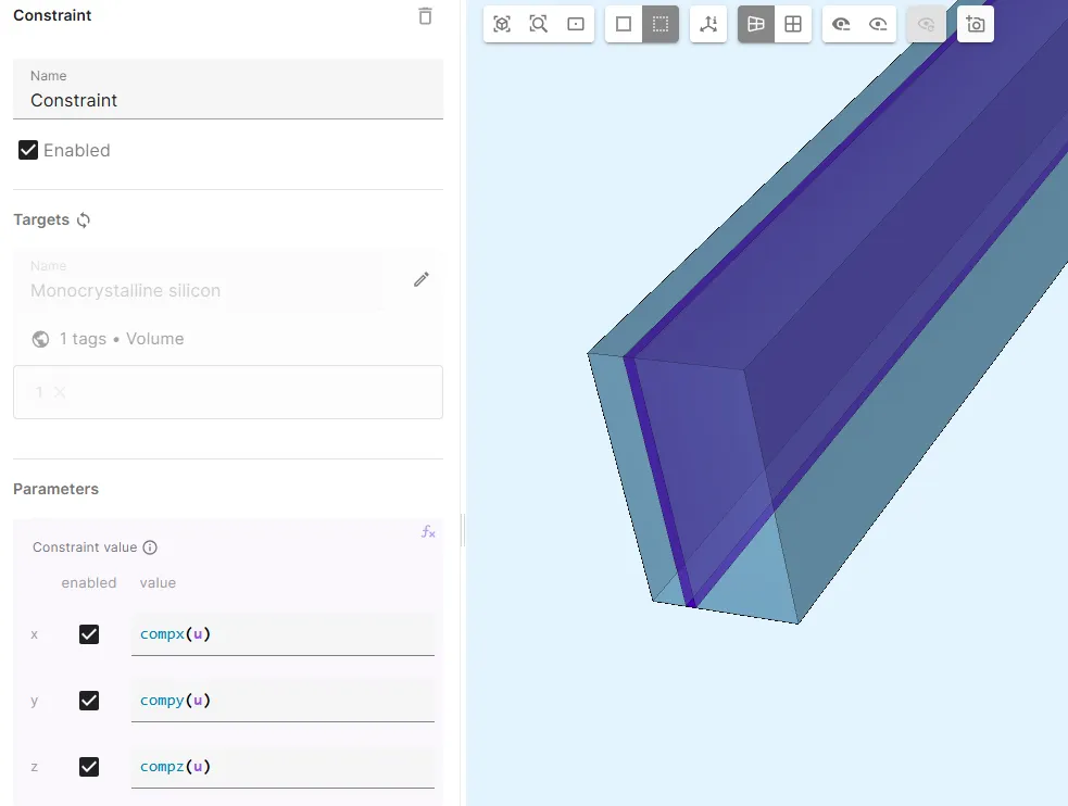
- As Target, select the
- Add
Constraint 2.- As Target, select surfaces
7 - 9, 12 - 14. - Set Constraint value to
[1, 0; 1, 0; 1, 0]. 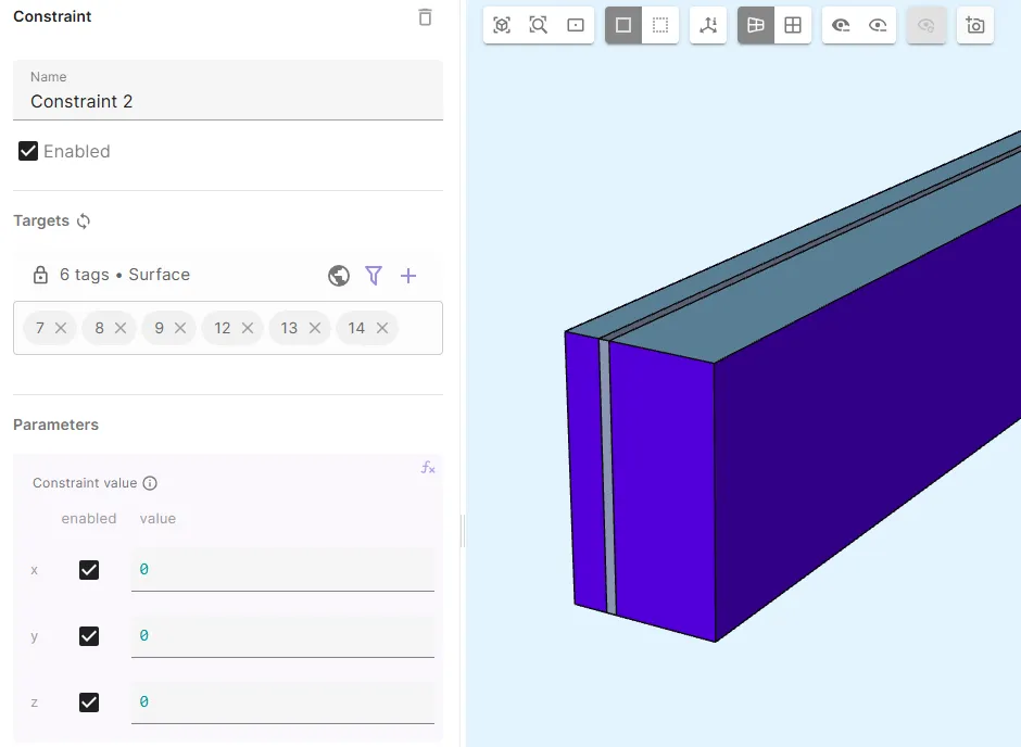
- As Target, select surfaces
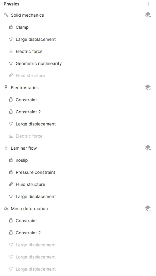
Finished physics tree:
Step 5 - Mesh the geometry
Section titled “Step 5 - Mesh the geometry”Go to the Simulations section.
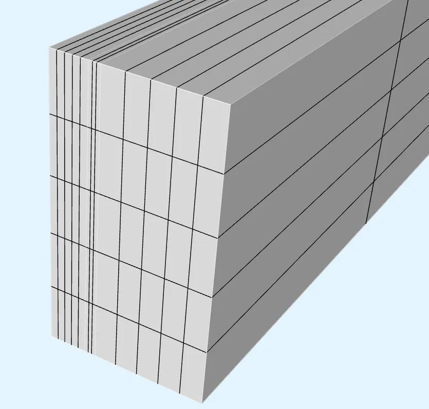
Create a new mesh using structured meshing:
-
Set Mesh quality to
Expert settings. -
Add 3
Volumetransfinite mesh entities, each targeting a different volume in the geometry. -
For the transfinite entity targeting volume
1, set the segment counts A, B and C as5,3and10, respectively. -
For the transfinite entity targeting volume
13, set the segment counts A, B and C as5,5and10, respectively. -
For the transfinite entity targeting volume
25, set the segment counts A, B and C as5,5and10, respectively. -
Save the settings & mesh.
Finished mesh:
Step 6 - Simulate
Section titled “Step 6 - Simulate”In the Simulations section, create a new simulation:
- In Simulation settings:
- Set Analysis type to
Multiharmonic. - Set Fundamental frequency to
freq. - Set Harmonics to
1 2 3 4 5 6 7 8 9. - Set Number of FFT samples to
20. - Set Node count to
10. - Use the default Node type (
1 CPU, 16 GB).
- Set Analysis type to
- In Mesh, select the mesh you created.
- In Inputs:
- Add
freq sweep.- Set Override expression to
linspace(20, 20000, 20).
- Set Override expression to
- Add
Voltage sweep.- Set Override expression to
linspace(5, 25, 20).
- Set Override expression to
- Add
- Add Outputs to your liking.
Adding a THD output via scripting (optional)
Section titled “Adding a THD output via scripting (optional)”Once you have defined all the options, inputs and outputs for your simulation through the GUI, you can add a Total Harmonic Distortion (THD) custom output with scripting:
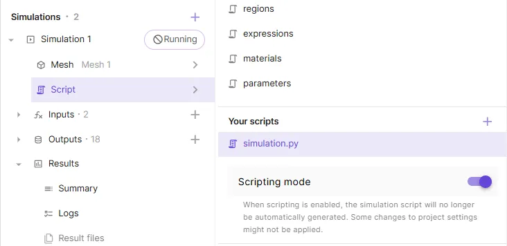
-
Enable scripting mode.
-
Add this snippet of code at the end of your
simulation.pyfile.########################################### THD_F CUSTOM VALUE OUTPUTprobe = [0,0,0]ui = []THD = 0for i in range(9):ui.append(qs.allinterpolate(reg.solid_mechanics, qs.harm(i+1, qs.compy(fld.u), 20), probe))if(i>2):THD = THD + ui[i]*ui[i]THD = qs.evaluate(qs.sqrt(THD/(ui[0]*ui[0]+ui[1]*ui[1]+1e-50)))qs.setoutputvalue("THD_F", THD)########################################## -
Save the script.
Your simulation is now ready to run.
Step 7 - Plot & visualize
Section titled “Step 7 - Plot & visualize”In the Simulations section, add plots to see value output results, or visualizations to see field output results.
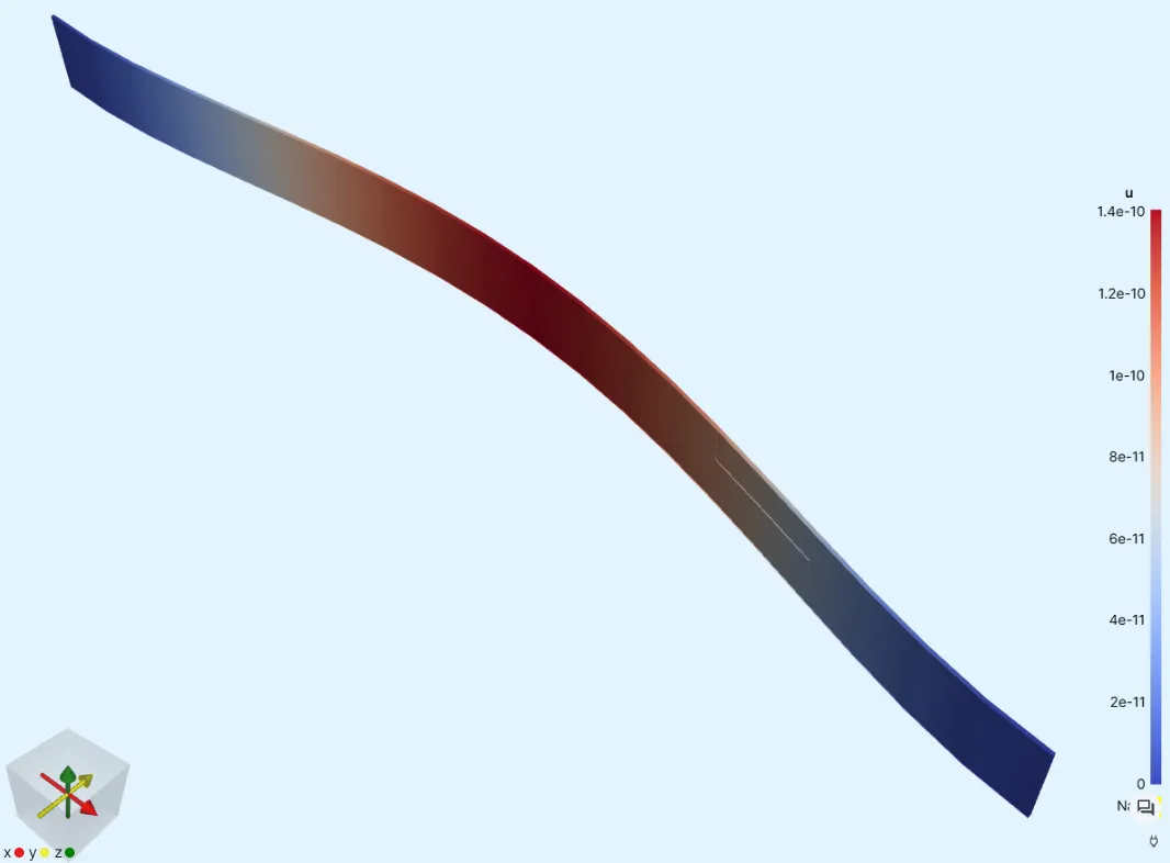
One visualization example is given below, generated with the following options:
- Field output:
- Displacement field
u harmonic 1 - Out of sweep subsimulations 0 - 19,
Simulation 0was used
- Displacement field
- Color preset:
- Cool to warm
- Warp:
- Scale factor
500000
- Scale factor
Results
Section titled “Results”Below are a few examples of simulation results post-processed with external software.
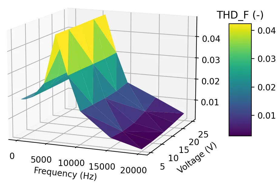
Plot 1: The custom value output THD_F plotted as a function of frequency and voltage
Animation 1: Displacement, microspeaker plate cut in half at the X-axis symmetry plane
Animation 2: Displacement of the complete microspeaker plate
References
Section titled “References”Footnotes
Section titled “Footnotes”-
Kaiser, B. et al. Concept and proof for an all-silicon MEMS micro speaker utilizing air chambers. Microsyst Nanoeng 5, 43 (2019). https://doi.org/10.1038/s41378-019-0095-9. ↩
-
Melnikov, A., Schenk, H.A.G., Monsalve, J.M. et al. Coulomb-actuated microbeams revisited: experimental and numerical modal decomposition of the saddle-node bifurcation. Microsyst Nanoeng 7, 41 (2021). https://doi.org/10.1038/s41378-021-00265-y ↩
-
Dr. Andrew Tweedie, Dr. Abhishek Deshmukh, Jukka Knuutinen. Faster and more reliable MEMS design with cloud-based multiphysics simulations. Quanscient webinars (2024). https://quanscient.com/events/mems-webinar-06-24/register ↩