Packaging 001 - FCBGA free warpage
In this example, warpage and thermal stresses due to thermal expansion are considered for a Flip Chip Ball Grid Array (FCBGA) semiconductor packaging solution.


Simulation setup guide
Section titled “Simulation setup guide”Below, you’ll find a simplified guide for setting this up in Quanscient Allsolve.
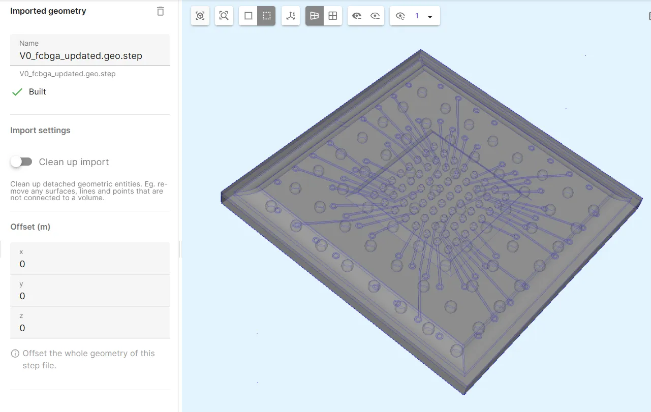
Step 1 - Import the geometry
Section titled “Step 1 - Import the geometry”In the Geometry section, start by importing a .step file for your FCBGA model:
File download link: fcbga.step
Step 2 - Define variables
Section titled “Step 2 - Define variables”Go to the Common sidebar.
Define variables:
| Name | Description | Expression |
|---|---|---|
| Tsf | Stress free temperature [K] | 273 + 150 |
| Tend | Final temperature [K] | 273 + 25 |
Step 3 - Define shared regions
Section titled “Step 3 - Define shared regions”Continuing in the Common sidebar, define the following 9 shared regions:
- Define the ball grid array volume shared region
v1_bga.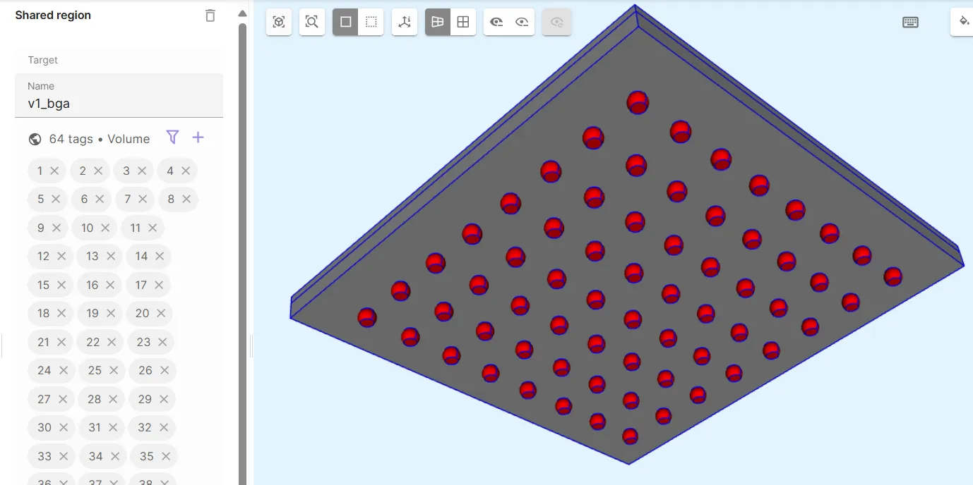
-
Define the substrate volume shared region
v2_substrate.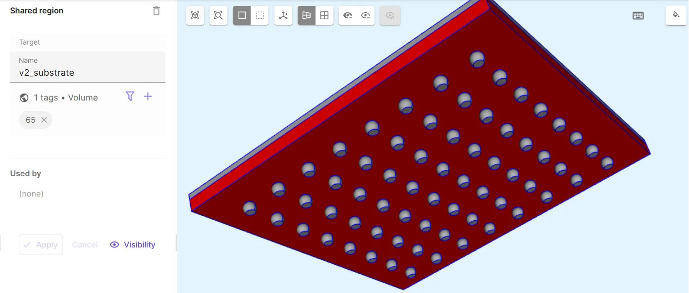
-
Define the cut rails volume shared region
v3_cutrails.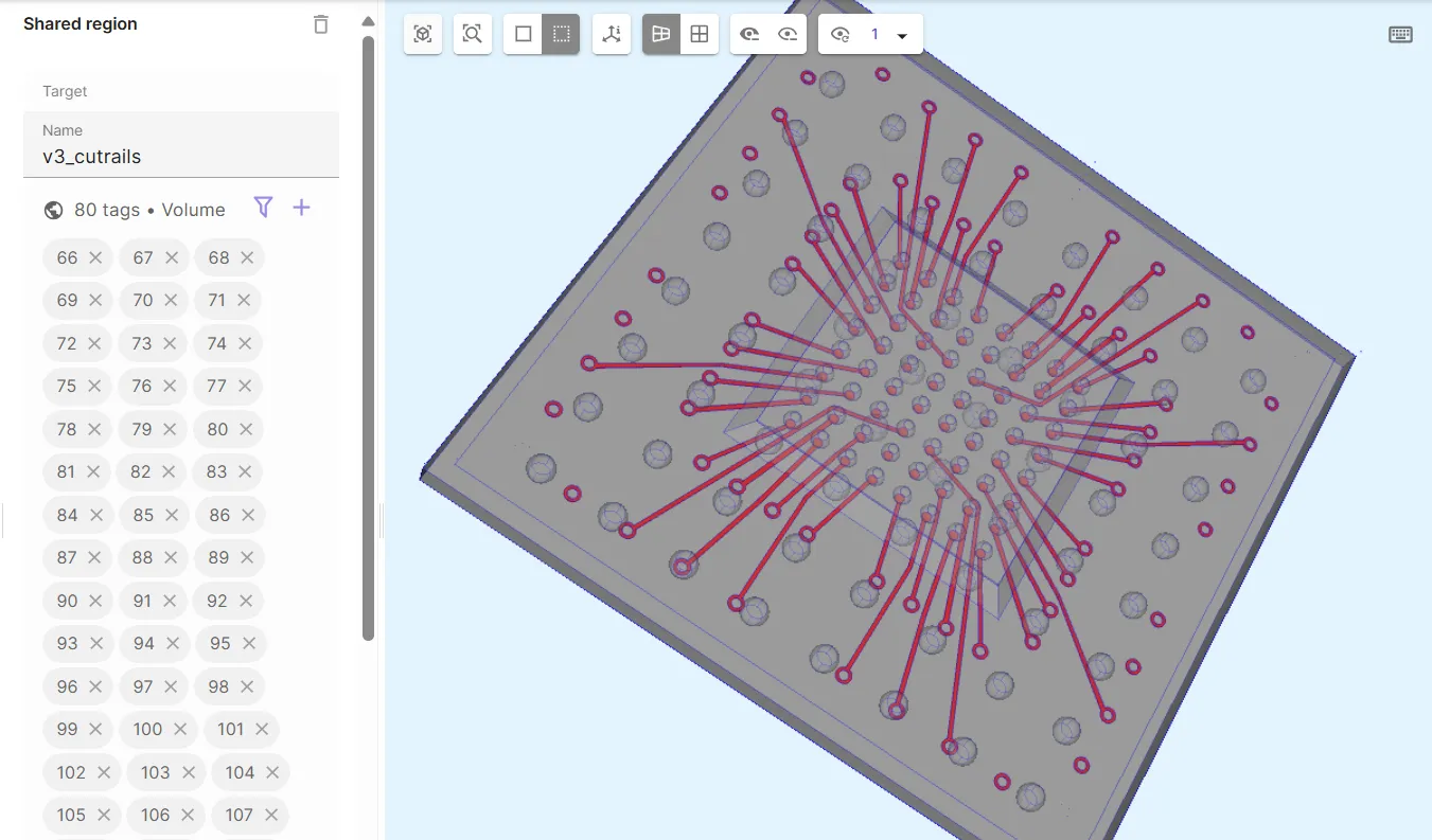
-
Define the micro bumps volume shared region
v4_microbumps.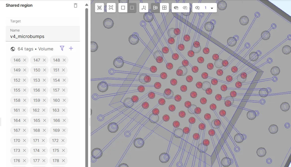
-
Define the flip chip volume shared region
v5_dieFC.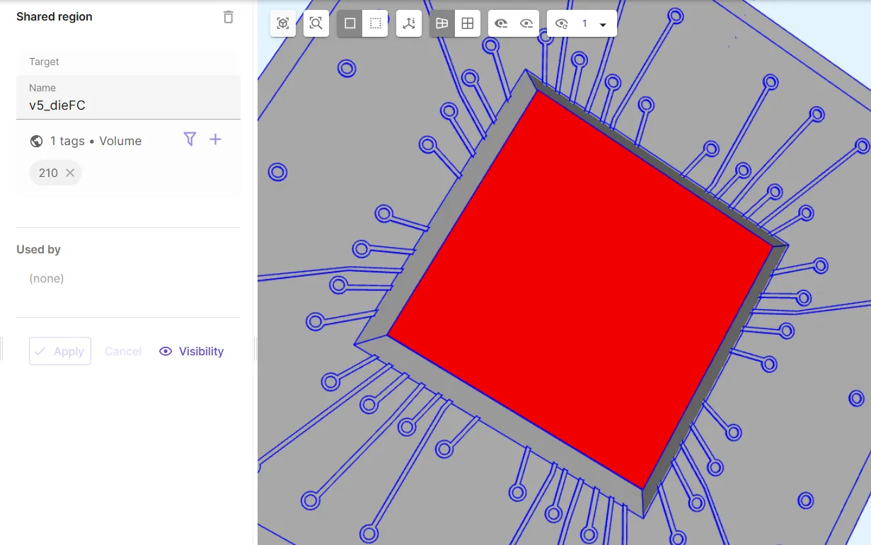
-
Define the heat spreader volume shared region
v6_heatspreader.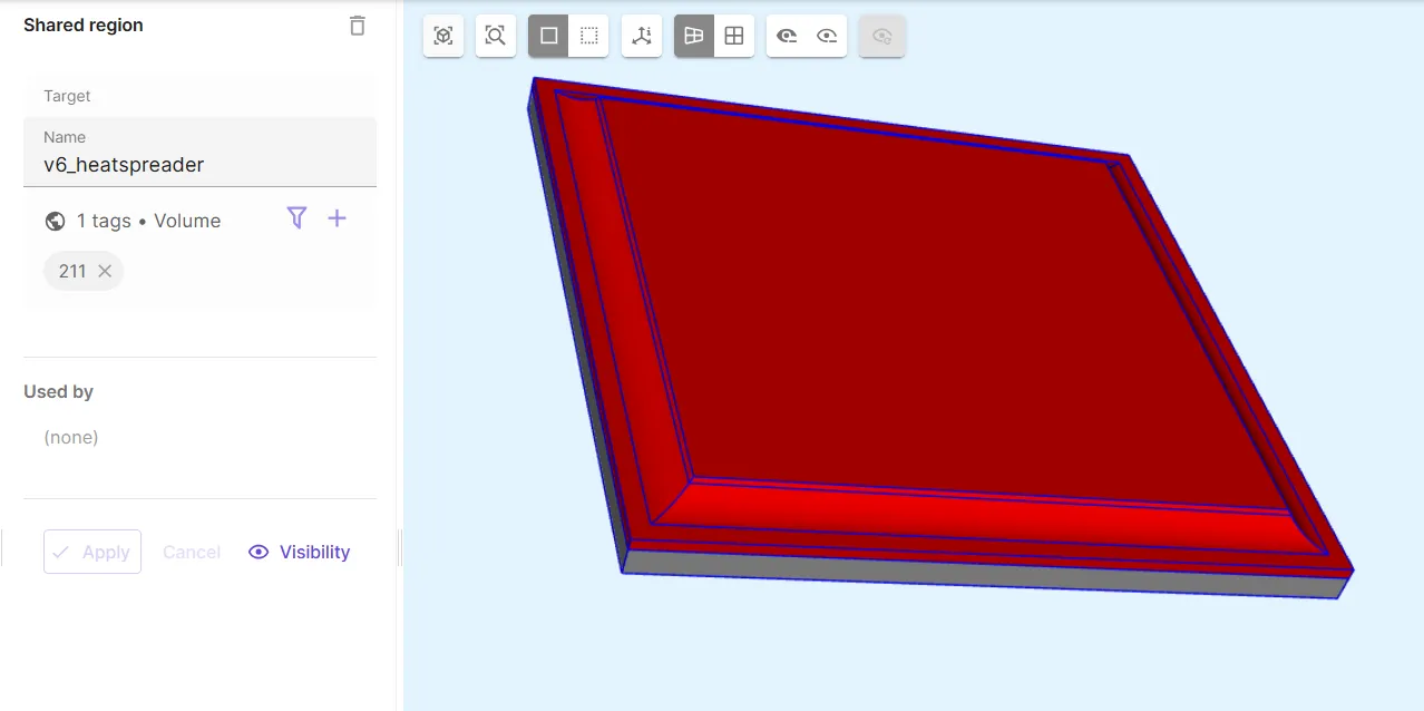
-
Define the underfill volume shared region
v7_underfill.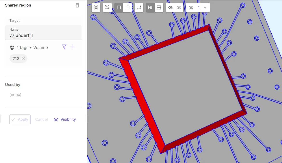
-
Define the solder balls volume shared region
solderballs, which contains all volumes from thev1_bgaandv4_microbumpsregions.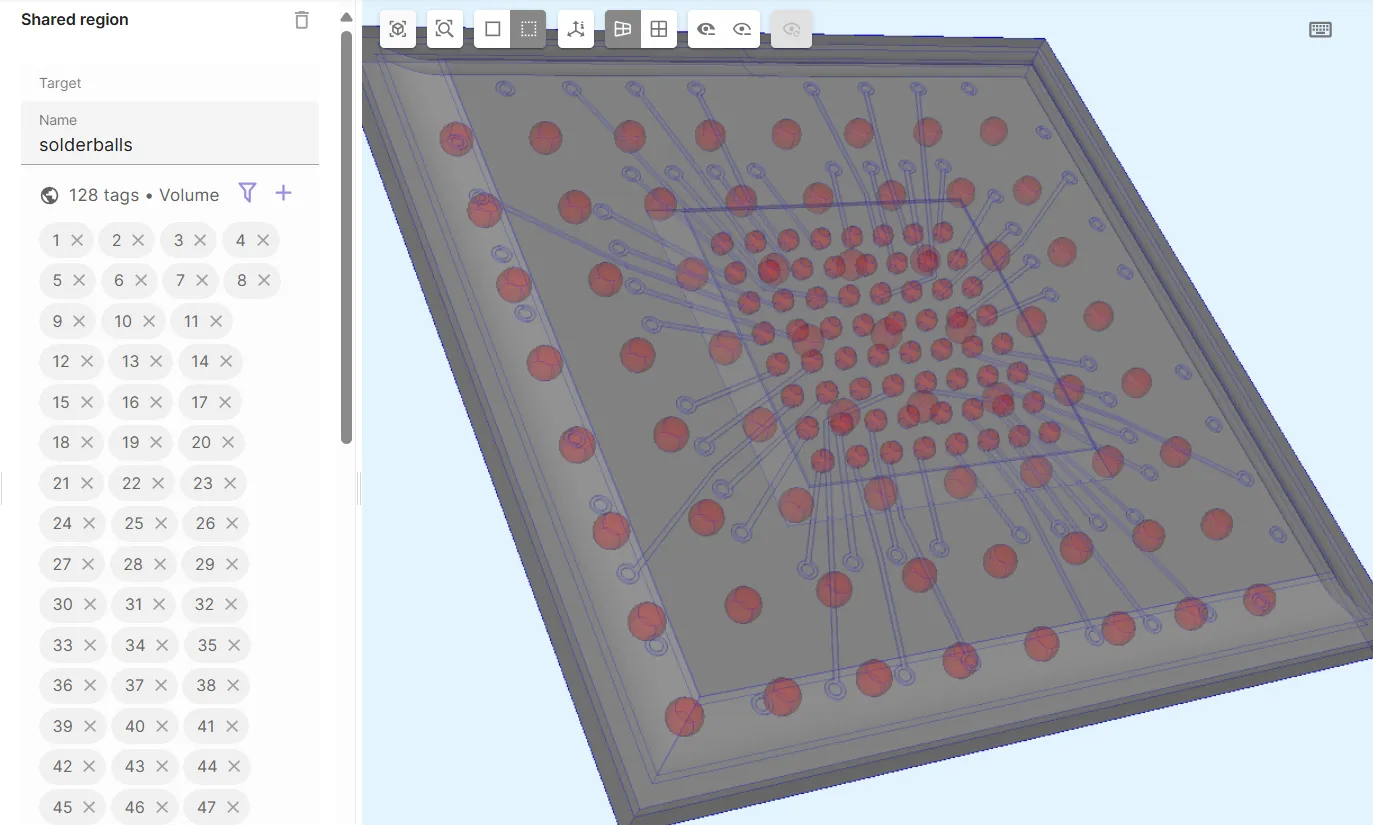
- Define the all regions volume shared region
allreg, which contains all volumes in the model.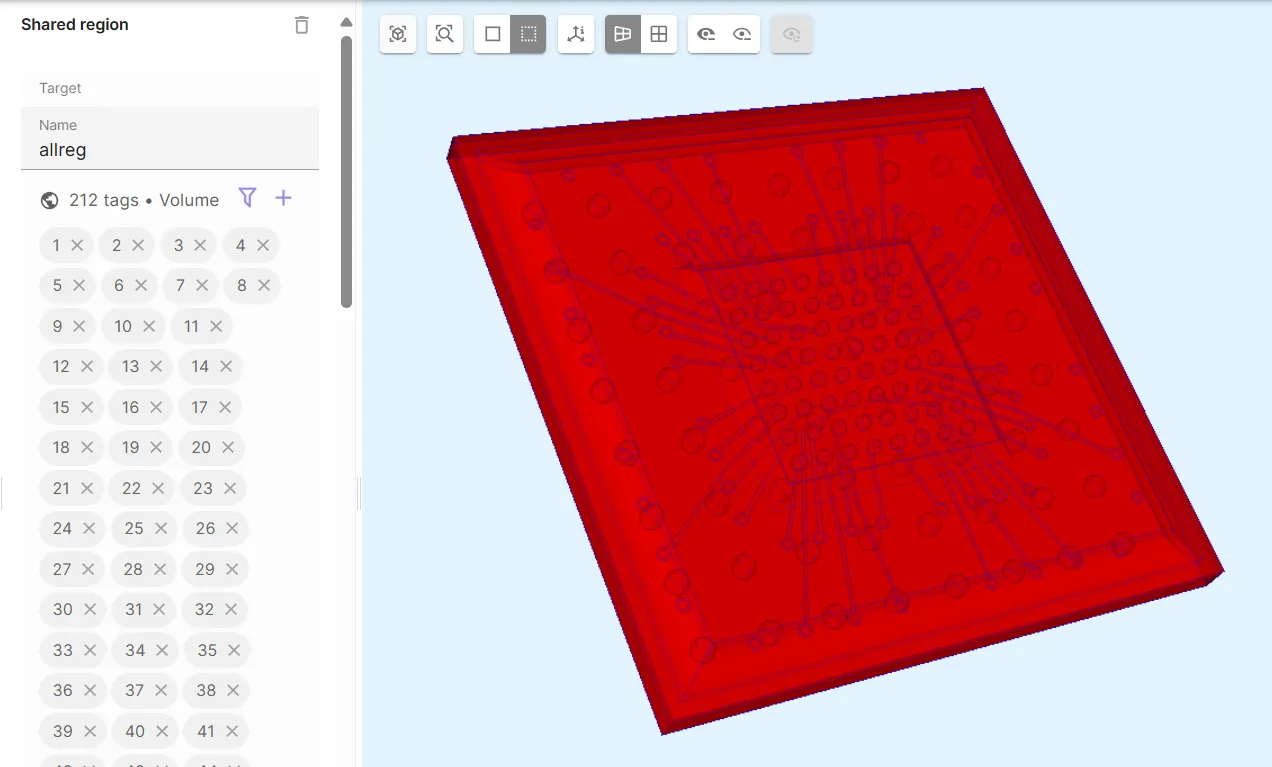
Step 4 - Define the materials
Section titled “Step 4 - Define the materials”Finally, in the Physics section, define the model materials.
In this example, 3 new materials are created:
The 3 following predefined materials are also used:
- Aluminium
- Integrated heat spreader
- Copper
- Cut rails
- Silicon dioxide
- Flip chip
See the dedicated subsections below for detailed material definitions.
Material 1 - SAC305
Section titled “Material 1 - SAC305”The SAC305 material is defined for the FCBGA solder balls.
Create a new material:
| Name | Abbreviation | Material color | Target |
|---|---|---|---|
Solder ball | SAC305 | Light gray | The solderballs shared region |
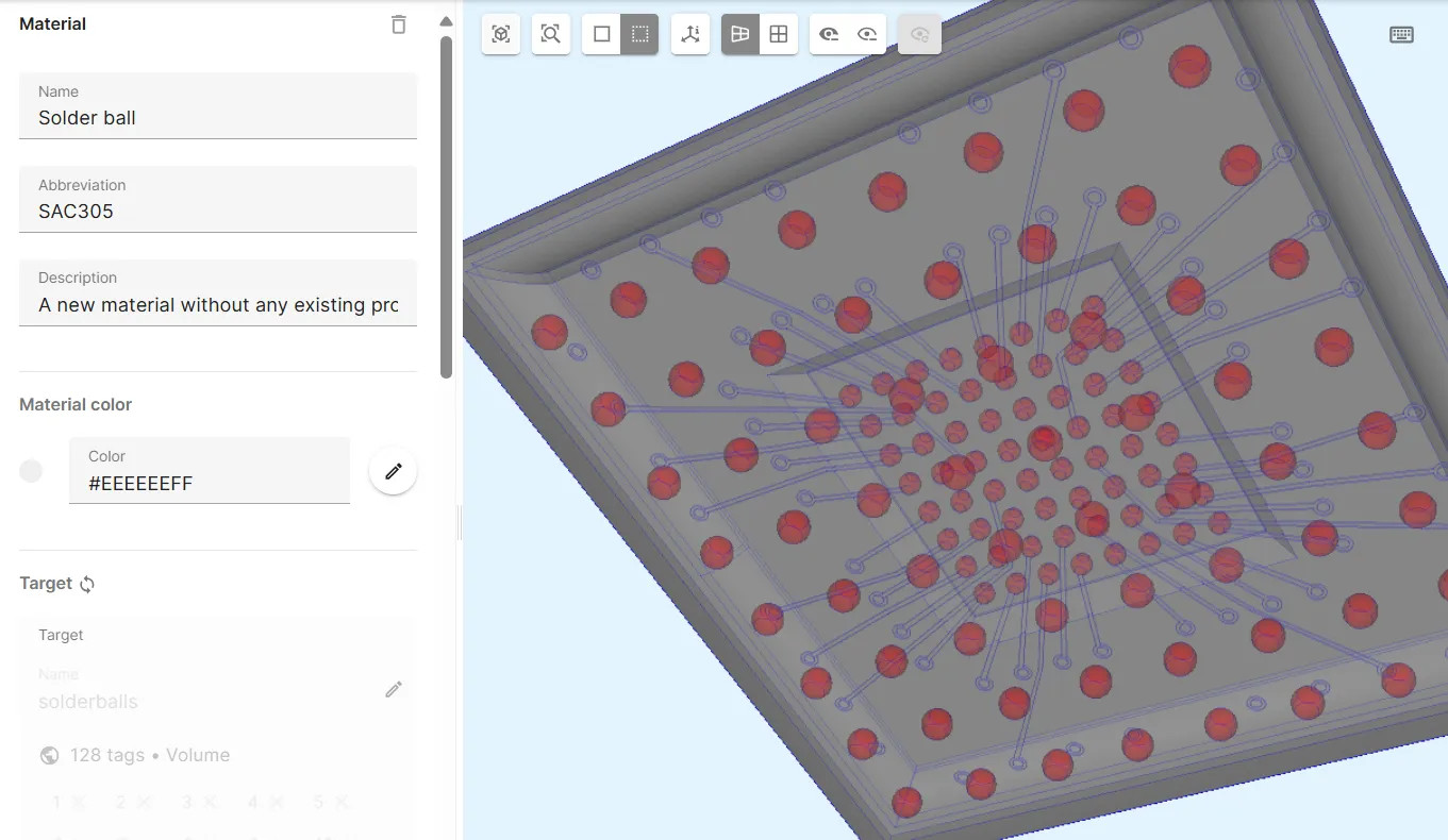
Add properties to the material:
| Coefficient of thermal expansion | Elasticity matrix | Thermal conductivity |
|---|---|---|
20e-6 | Poisson’s ratio: 0.3 | 60 |
Young’s modulus: 45e9 |
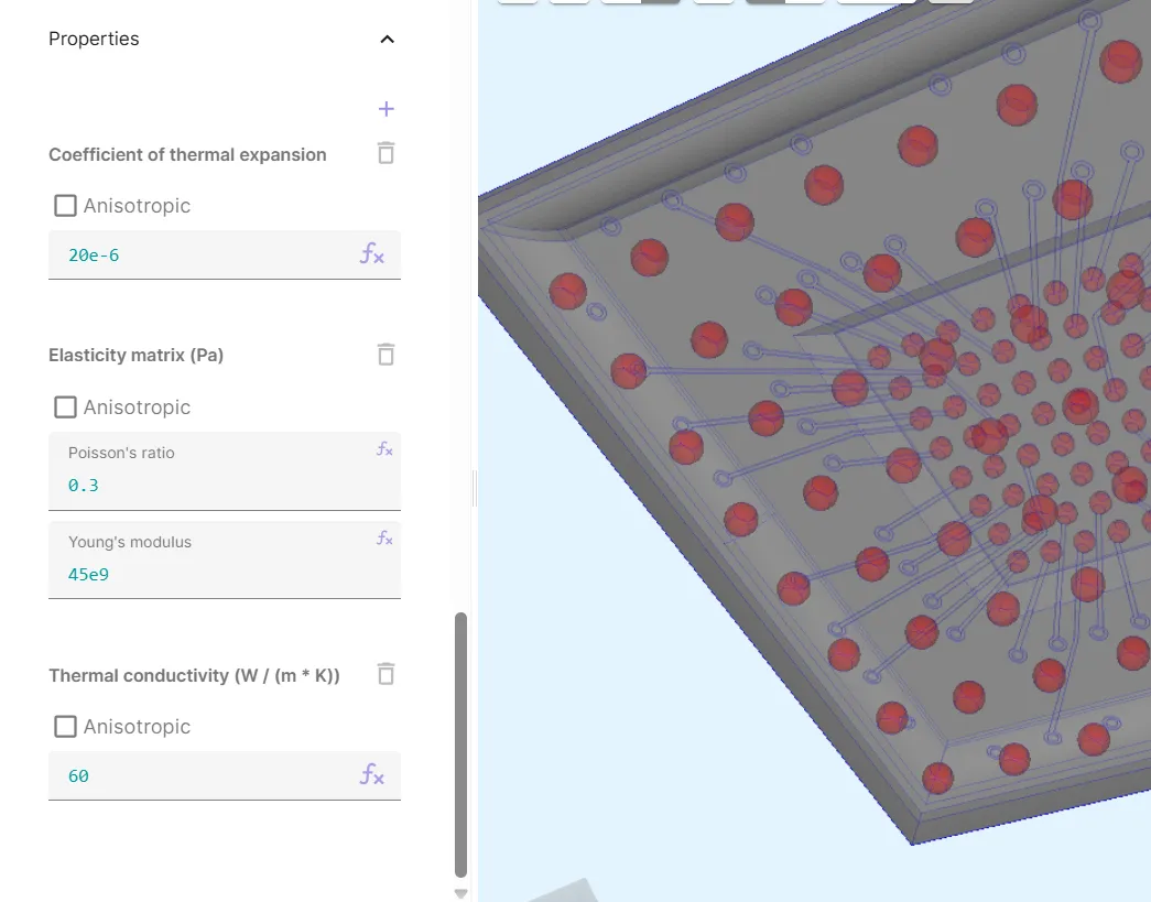
Now, your SAC305 material is defined.
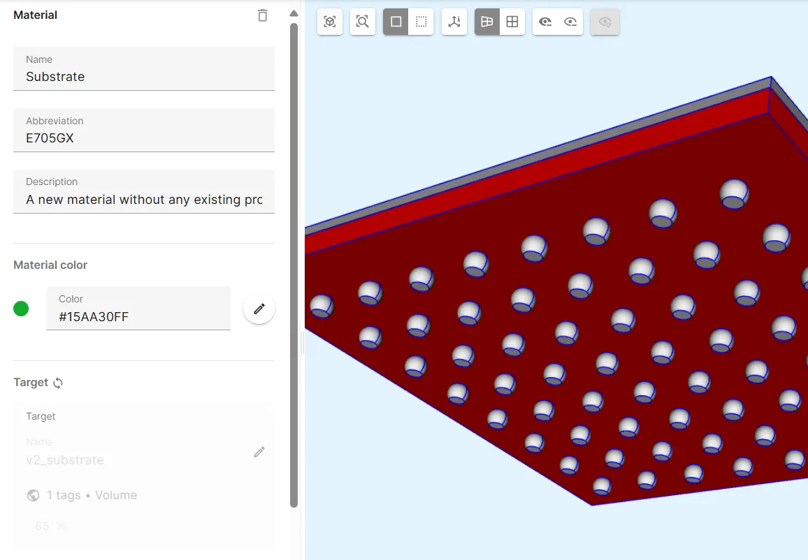
Material 2 - E705GX
Section titled “Material 2 - E705GX”The E705GX material is defined for the FCBGA substrate.
Create a new material:
| Name | Abbreviation | Material color | Target |
|---|---|---|---|
Substrate | E705GX | Green | The v2_substrate shared region |
Add properties to the material:
| Coefficient of thermal expansion | Elasticity matrix | Thermal conductivity |
|---|---|---|
ifpositive(T-(260+273), 7.8e-6, 2e-6) | Poisson’s ratio: 0.3 | 0.65 |
Young’s modulus: ifpositive(T-(260+273), 16e9, 25e9) |
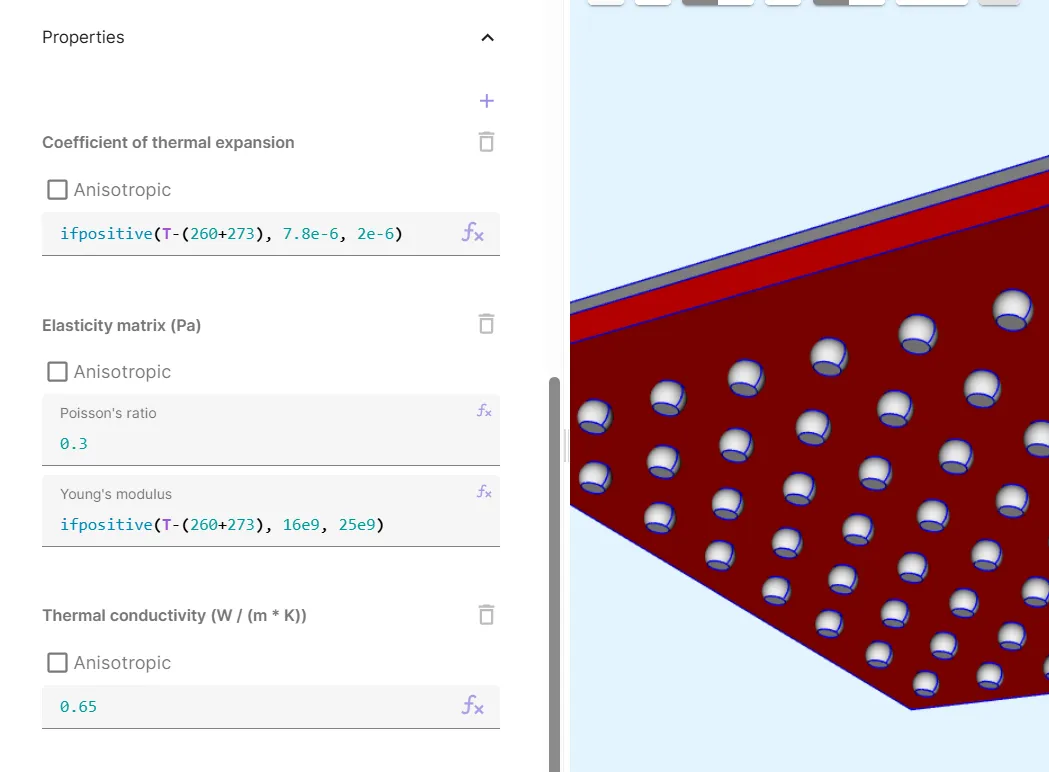
Now, your E705GX material is defined.
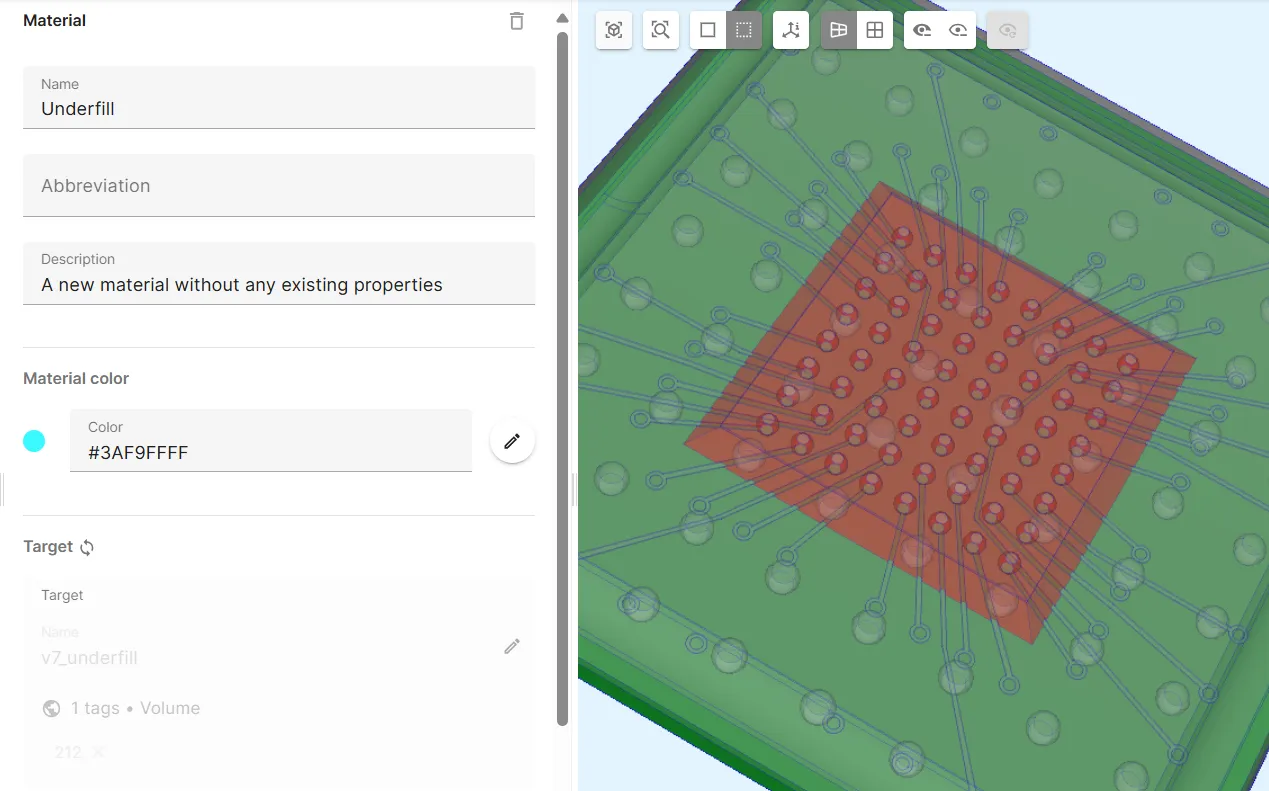
Material 3 - Underfill
Section titled “Material 3 - Underfill”The Underfill material is defined for the FCBGA underfill.
Create a new material:
| Name | Abbreviation | Material color | Target |
|---|---|---|---|
Underfill | Cyan | The v7_underfill shared region |
Add properties to the material:
| Coefficient of thermal expansion | Elasticity matrix | Thermal conductivity |
|---|---|---|
ifpositive(T-(140+273), 80e-6, 20e-6) | Poisson’s ratio: 0.3 | 0.52 |
Young’s modulus: ifpositive(T-(140+273), 0.65e9, 10e9) |
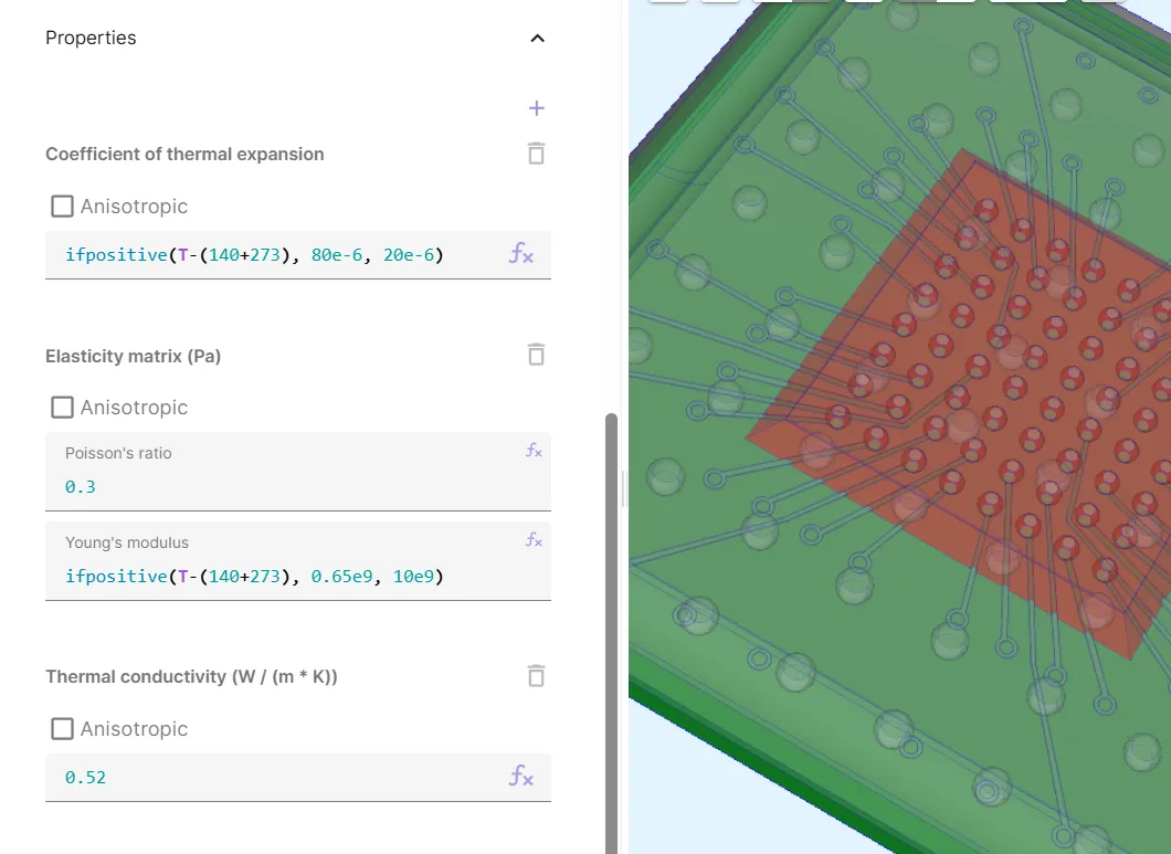
Now, your Underfill material is defined.
Material 4 - Aluminium
Section titled “Material 4 - Aluminium”The Aluminium material is assigned to the FCBGA heat spreader.
- Pick
Aluminiumfrom the materials library. - Select the
v6_heatspreadershared region as target.
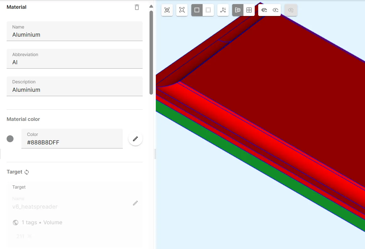
Now, your Aluminium material is defined.
Material 5 - Copper
Section titled “Material 5 - Copper”The Copper material is assigned to the FCBGA cut rails.
- Pick
Copperfrom the materials library. - Select the
v3_cutrailsshared region as target.
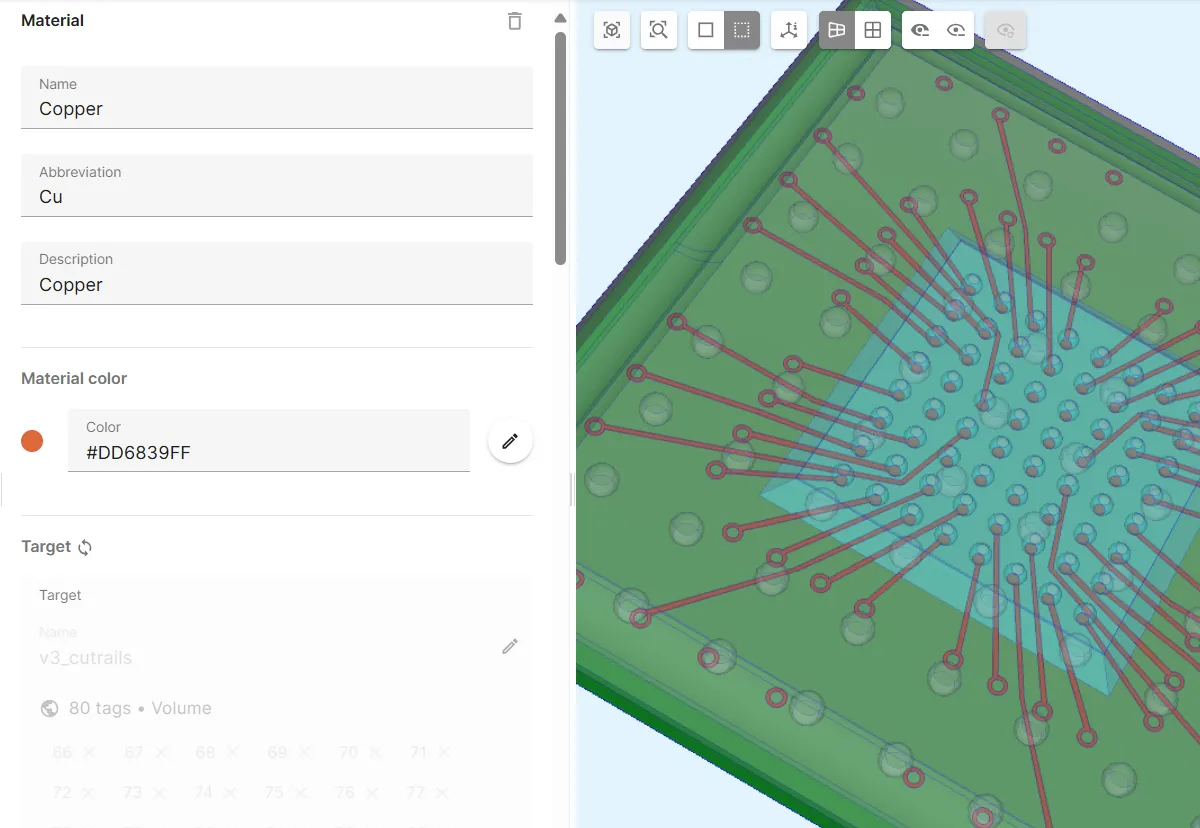
Now, your Copper material is defined.
Material 6 - Silicon dioxide
Section titled “Material 6 - Silicon dioxide”The Silicon dioxide material is assigned to the FCBGA flip chip.
- Pick
Silicon dioxidefrom the materials library. - Select the
v5_dieFCshared region as target.
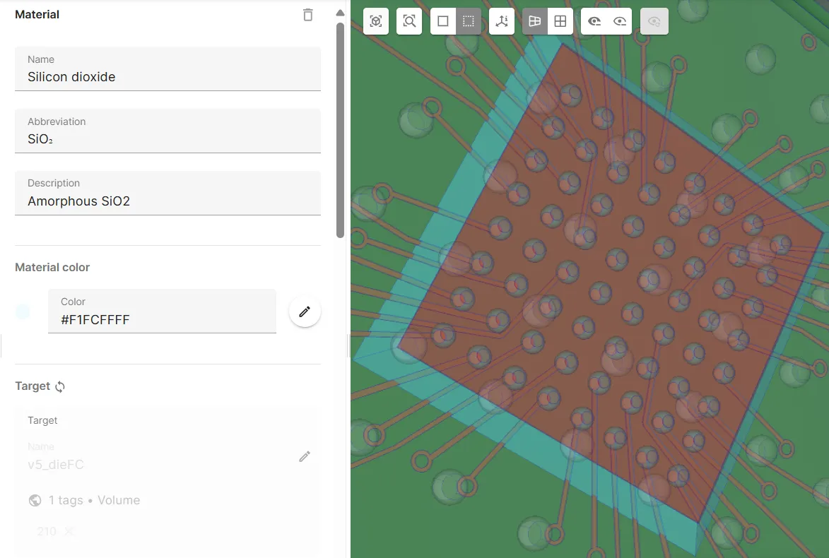
Now, all your model materials are defined.
Step 5 - Define the physics
Section titled “Step 5 - Define the physics”Proceed to the Physics section to define the project physics, interactions and couplings.
In this example, two physics are required:
See the corresponding subsections for detailed definitions.
Physics 1 - Solid mechanics
Section titled “Physics 1 - Solid mechanics”- Let the solid mechanics target default to the whole geometry.
- Add the Solid mechanics - Heat solid coupling
Thermal expansion.- As target, select the shared region
allreg, which contains all volumes in the model. - Set Reference temperature to
Tsf.
- As target, select the shared region
- Add Constraint and name it as
Uxyz constraint.- As target, choose a bottom corner point on the substrate volume
- Set Constraint value to
[1, 0; 1, 0; 1, 0].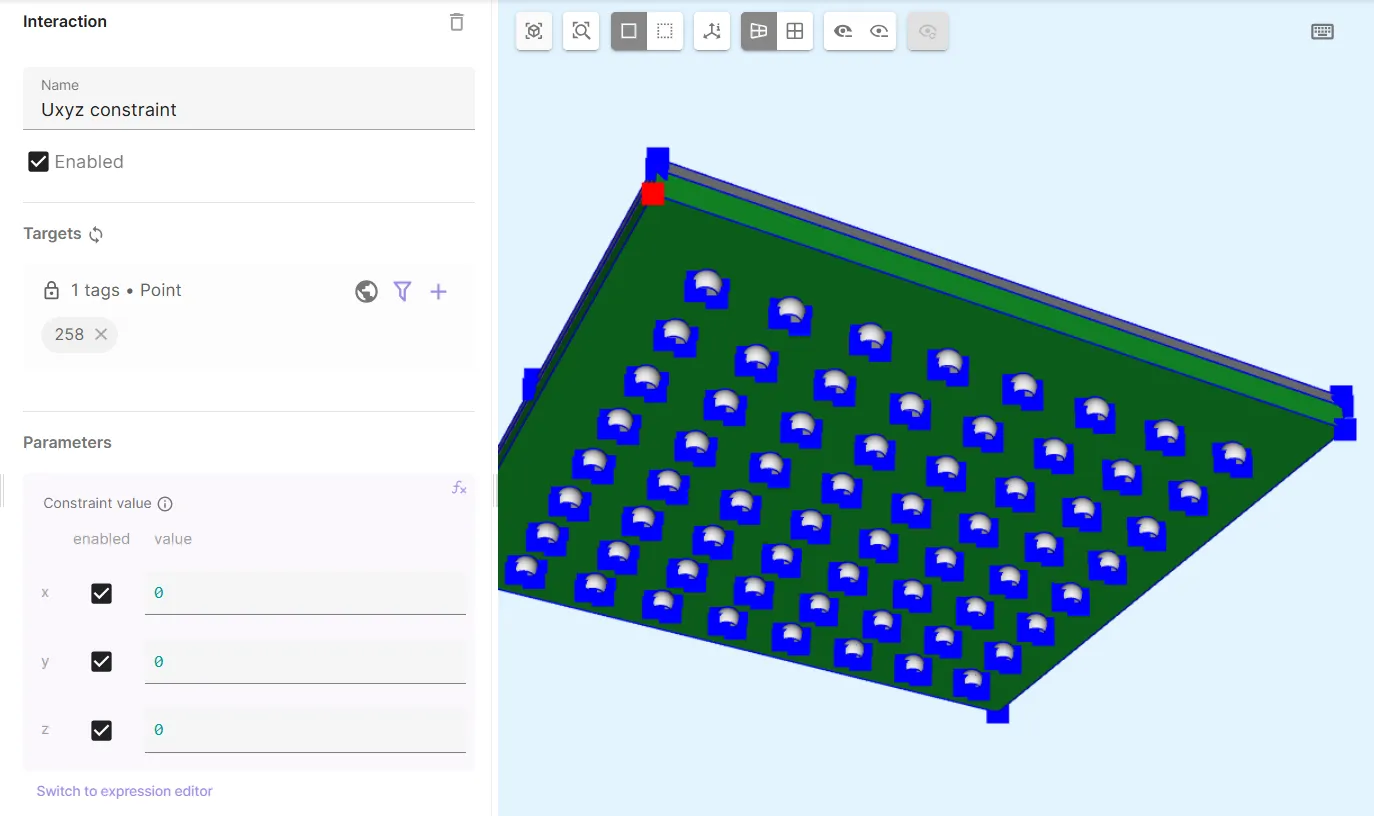
- Add another Constraint and name it as
Uyz constraint.- As target, choose another bottom corner point on the substrate volume
- Set Constraint value to
[0, 0; 1, 0; 1, 0].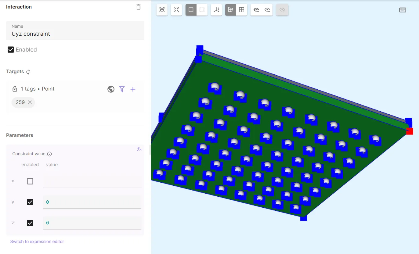
- Add a third Constraint and name it as
Uz constraint.- As target, choose a third bottom corner point on the substrate volume
- Set Constraint value to
[0, 0; 0, 0; 1, 0].
Now, your solid mechanics are defined.
Physics 2 - Heat solid
Section titled “Physics 2 - Heat solid”- Let the heat solid target default to the whole geometry.
- Add
Constraint.- As Target, select the shared region
allreg, which contains all volumes in the model. - Set Constraint value to
Tend.
- As Target, select the shared region
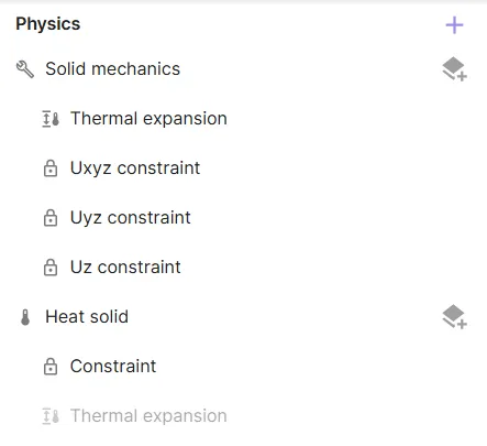
Now, all your physics, as well as their interactions and couplings are defined. Before moving on, check that your physics tree looks like in the image below.
Step 6 - Generate the mesh
Section titled “Step 6 - Generate the mesh”Proceed to the Simulations section and create a new mesh:
- Set Mesh quality to
Expert settings. - Set Scale factor to
2. - Click
Apply and mesh. - Once meshing is finished, click
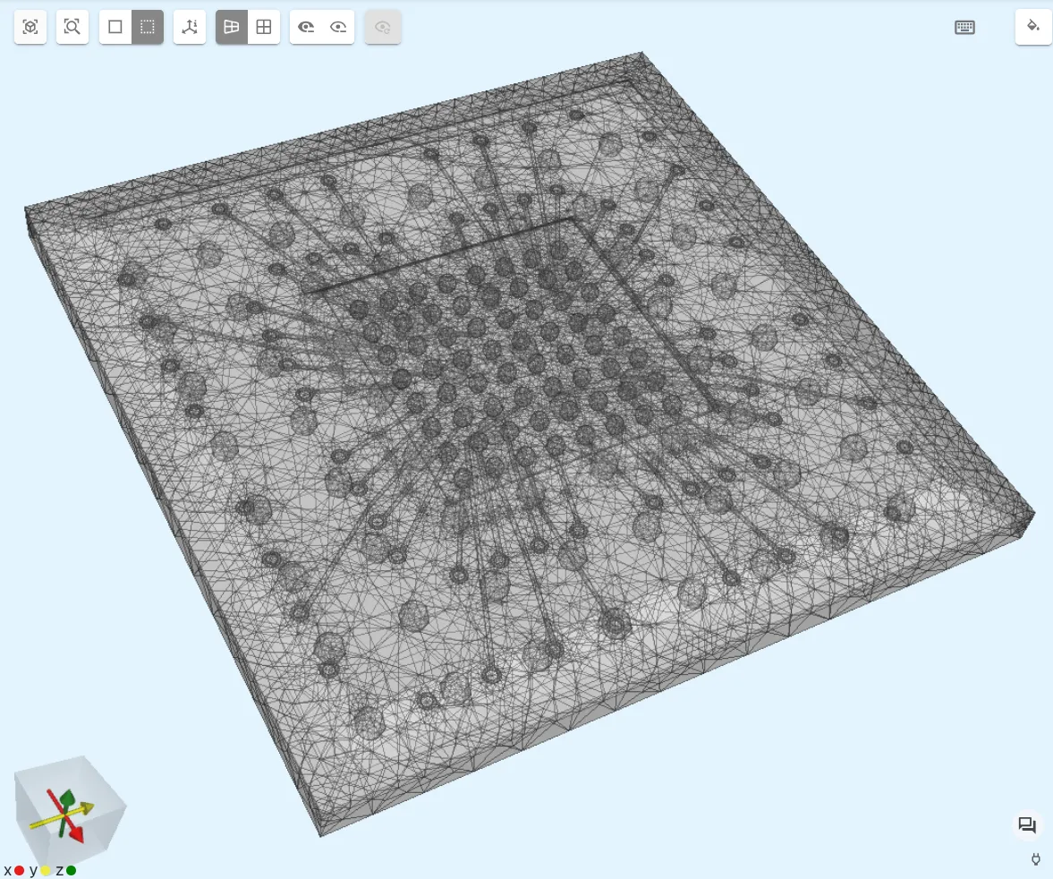
Show preview.
In the preview, your finished mesh should look something like in the image below.
Step 7 - Simulate
Section titled “Step 7 - Simulate”In the Simulations section, create a new simulation:
- In Simulation settings:
- Set Analysis type to
Static. - Set Node count to
10. - Set Node type to
1 CPU, 16 GB.
- Set Analysis type to
- In Mesh, select the mesh you generated in step 6.
- In Outputs:
- Add
ufield output.- Enable
skin only.
- Enable
- Add
Your simulation is ready to run.
Step 8 - Plot & visualize
Section titled “Step 8 - Plot & visualize”In the Simulations section, add plots to see value output results, or visualizations to see field output results.
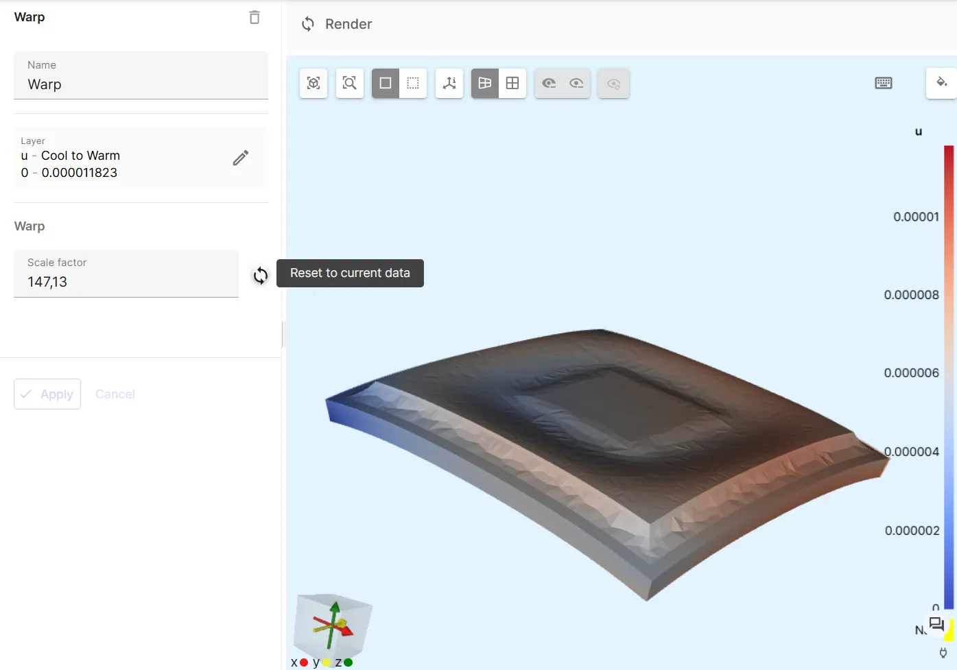
To visualize the u field output, for example, add a new visualization:
- Click
+next to Visualizations. - Click
+next to Visualization 1 and Select fieldu. - Click
+next to u and selectWarp. - Click
Reset to current datanext to Scale factor. - Click
Render.
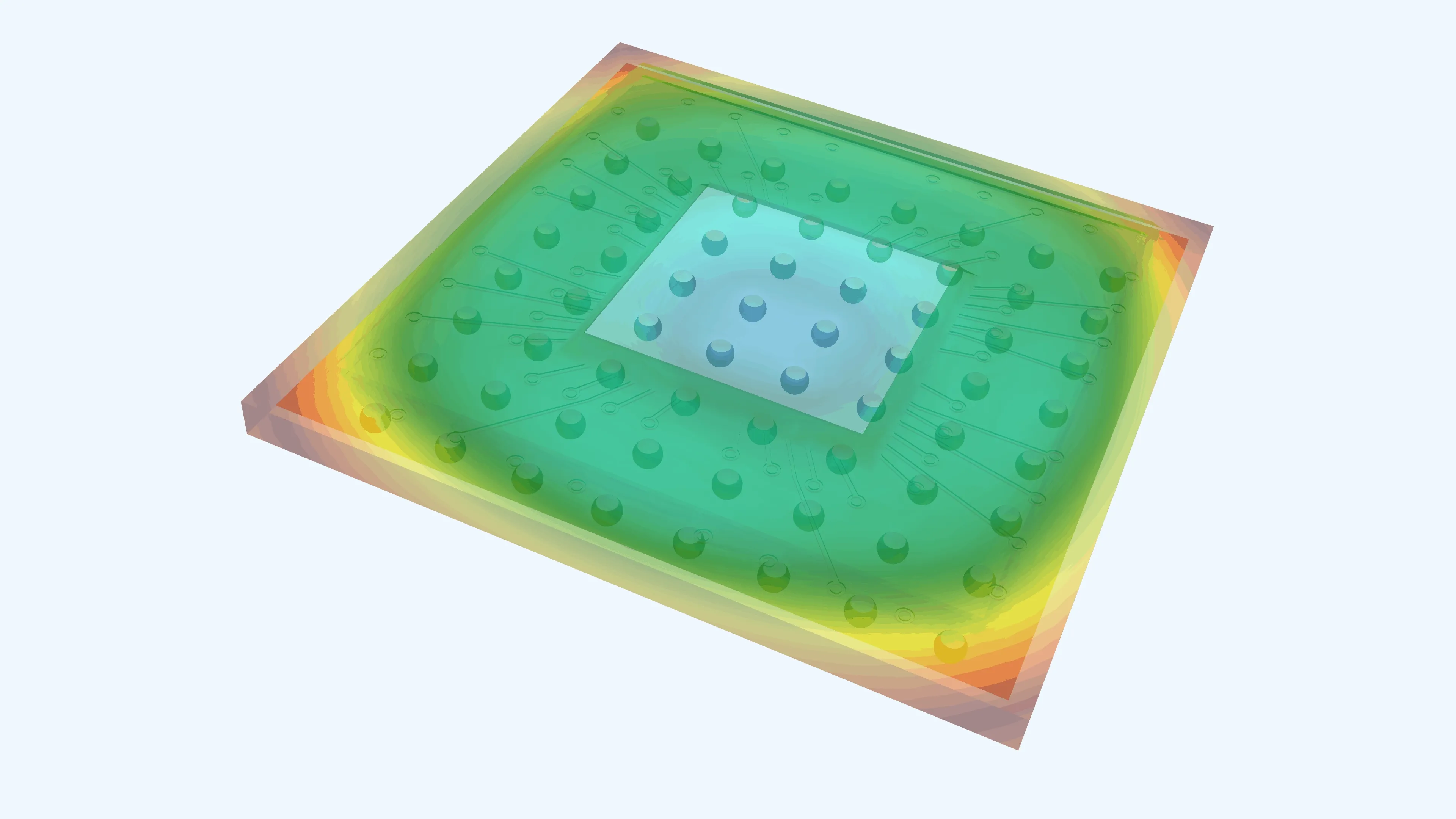
Results
Section titled “Results”Below is an example of warpage results post-processed to an animation.