Simulations
In Quanscient Allsolve, simulations can be created and modified in the Simulations section.
Projects can have more than one simulation, and new ones can be created by clicking + next to Simulations.
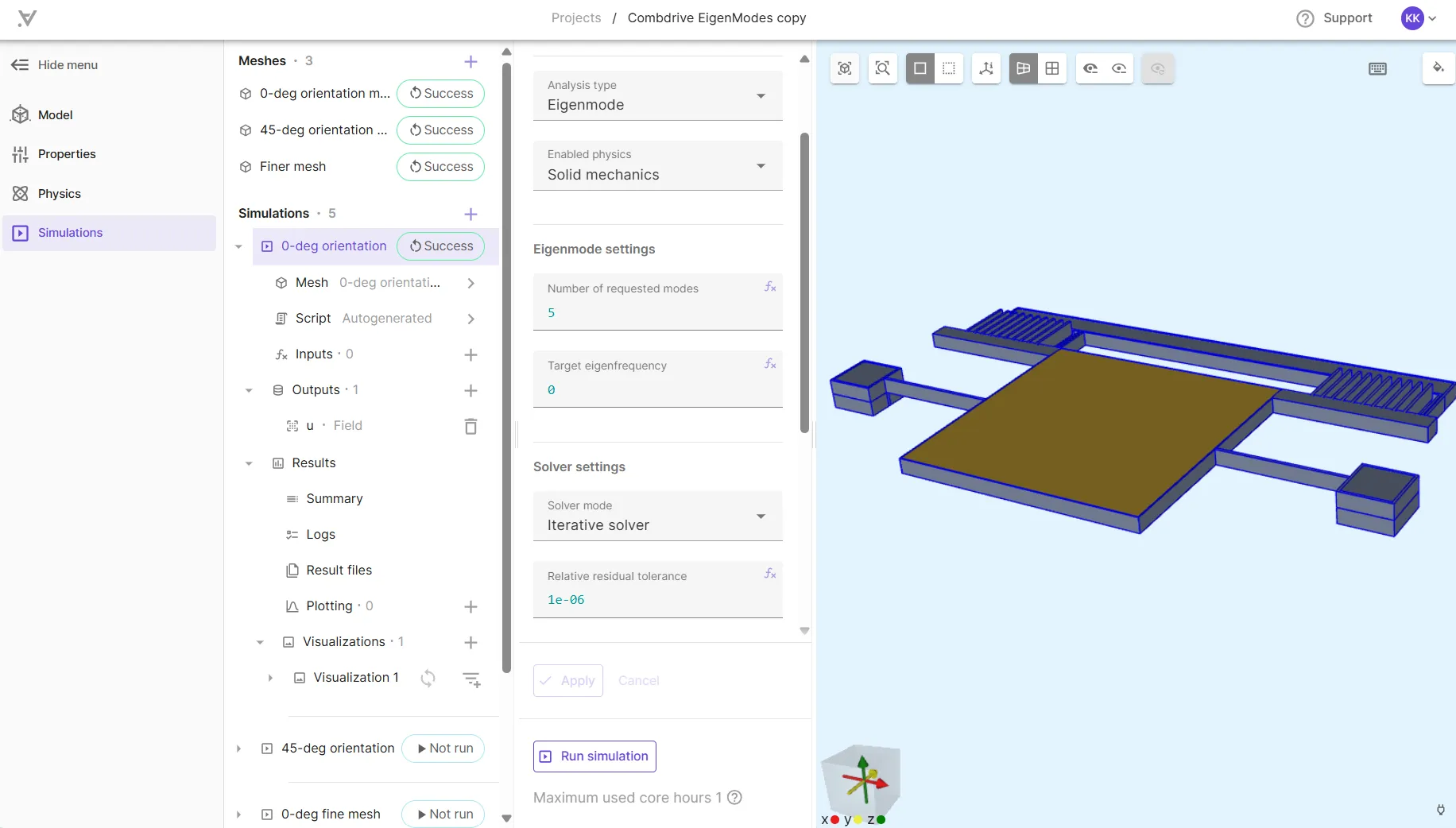
You can also create a new simulation by copying an existing one.
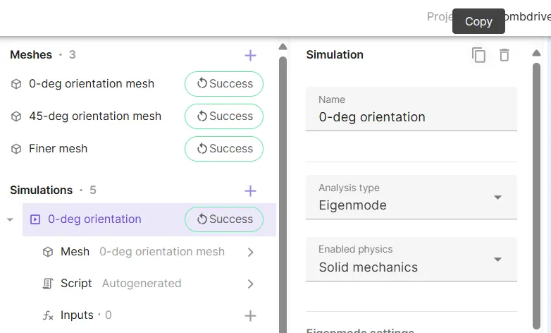
This comes in handy when you wish to create multiple simulations with similar options.
Introduction to simulations
Simulations in Allsolve have a variety of features, options and parameters to choose from. To introduce them, a subsection is dedicated to each one below.
Analysis types
One feature that sets Quanscient Allsolve apart from other multiphysics simulation software, is the variety of analysis types it offers. There are five different analysis types available for simulations:
- Steady state
- Time-independent systems
- Harmonic
- Sinusoidal input
- For linear problems
- Multiharmonic
- Input is a combination of multiple sinusoidal frequencies
- For nonlinear problems
- Transient
- Time-dependent systems
- Time-stepping
- Eigenmode
- Determine the natural frequencies and associated mode shapes of a system
Below, we’ll look at how to choose the analysis type for a simulation.
Choosing analysis type
The analysis types are very situational, and choosing the right analysis type depends on the nature of the problem at hand. Check the compatibility of analysis types and physics in the table below:
| Steady state | Harmonic | Multiharmonic | Transient | Eigenmode | |
|---|---|---|---|---|---|
| Solid Mechanics | ☑️ | ☑️ | ☑️ | ☑️ | ☑️ |
| Current flow | ☑️ | ☑️ | ☑️ | ||
| Acoustic waves | ☑️ | ☑️ | ☑️ | ||
| Electrostatics | ☑️ | ☑️ | ☑️ | ||
| Electromagnetic waves | ☑️ | ||||
| Magnetism A | ☑️ | ☑️ | ☑️ | ||
| Magnetism φ | ☑️ | ☑️ | ☑️ | ||
| Magnetism H | ☑️ | ☑️ | |||
| Laminar flow | ☑️ | ☑️ | |||
| Heat solid | ☑️ | ☑️ | ☑️ | ||
| Heat fluid | ☑️ | ☑️ | |||
| Elastic waves | ☑️ | ☑️ | |||
| Mesh deformation | ☑️ | ☑️ | ☑️ |
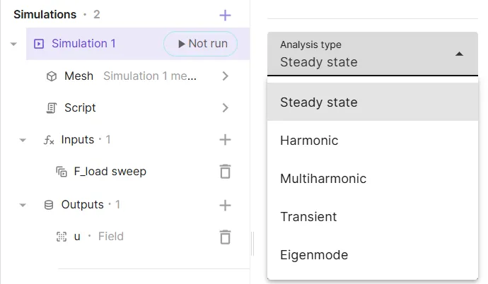
To choose your analysis type:
- Navigate to the
Simulationssection. - Click
+next to Simulations to create a new simulation. - Click
Analysis typeright below the simulation Name field. - Select your preferred analysis type in the drop-down list.
Below, we’ll delve deeper into each analysis type.
Steady state
Steady state analysis studies systems where the filed variables do not change over time. The partial time derivative term in the partial differential equation is assumed to be zero. You can think of it like a snapshot of a system after all the initial fluctuations have settled.
Steady state analysis is ideal for problems where the system is stable and the goal is to determine a final equilibrium state.
Harmonic
Harmonic analysis studies systems that respond to a sinusoidal input (e.g., a force or vibration) with a sinusoidal output.
Harmonic analysis is great for analyzing systems that experience simple periodic vibrations or oscillations. It helps determine the system’s response at different frequencies. Hence, harmonic simulations are often used with frequency sweeps.
Multiharmonic
Multiharmonic analysis is an extension of harmonic analysis, and it considers systems where the input is not a single sinusoid but a combination of multiple frequencies.
Multiharmonic analysis is useful when dealing with complex systems that are excited by multiple frequencies simultaneously.
Transient
Transient analysis examines how a system evolves over time in response to changing conditions. It calculates the system’s response at various time steps.
Transient analysis is essential for problems where the system’s behavior changes dynamically with time.
Eigenmode
Eigenmode analysis is used to determine the natural frequencies (eigenfrequencies) and associated mode shapes (eigenmodes) of a system. These are the frequencies and modes at which the system tends to vibrate or oscillate naturally when subjected to an intial disturbance with no other external driving force.
Eigenmode analysis is important for understanding the dynamic characteristics of structures, determining potential resonance risks, and designing systems to avoid excessive vibrations or deformations.
Enabled physics
In the simulation options, below Analysis type, is Enabled physics. When clicked, a drop-down list with tickable boxes appears, like in the image below.
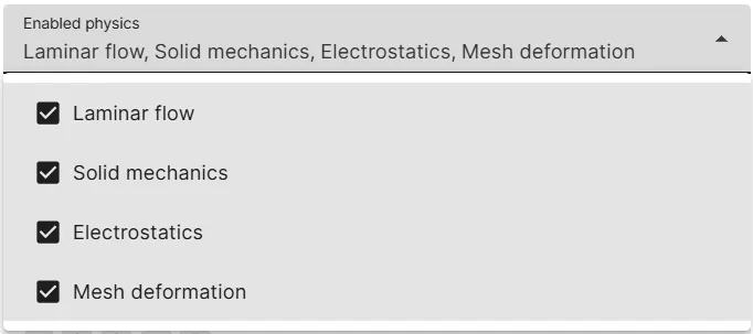
It includes the list of physics that were added in the project’s Physics section.
By default, all the defined physics are ticked as enabled.
If you want to disable certain physics in a simulation, untick those physics from the list.
Solver settings
In Quanscient Allsolve, there are two options for solver mode:
- Direct solver
- Uses a regular parallelization scheme to solve the linear system.
- Iterative solver
- Uses DDM to split the mesh into parts, which are then solved in parallel.
Below, we’ll look at the specifics of both solver modes, and how to choose between them.
Direct solver
The direct solver solves the linear system of equations directly using standard matrix decomposition techniques. It leverages regular parallelization schemes to distribute the computational load across multiple CPUs or nodes.
Strengths:
- Generally more robust and reliable, especially for smaller to medium-sized problems.
- Typically provides a precise solution without requiring many iterations.
Limitations:
- Can be computationally expensive and memory-intensive for large problems, as it requires storing and manipulating the entire linear system matrix.
- Scalability can be limited for extremely large models due to memory constraints.
Iterative solver
The iterative solver utilizes a DDM (Domain Decomposition Method), where the mesh is split into smaller subdomains, which are solved independently and in parallel. The iterative solver then coordinates the solution between adjacent subdomains, and continues iterating until the relative residual tolerance is subceeded.
Strengths:
- DDM enables efficient parallelization, as each subdomain can be processed on a separate CPU or node.
- More memory-efficient for large problems, as it only needs to store and manipulate smaller subdomain matrices.
- Often scales better for very large models due to the distributed nature of DDM.
Limitations:
- Convergence can be slower than with the direct solver, especially for ill-conditioned problems.
- Requires careful selection of solver parameters for optimal performance.
Which one to choose?
The choice between direct and iterative solvers depends on the specific simulation:
- Smaller to medium-sized problems: The direct solver is often a good starting point due to its robustness and relative ease of use.
- Large-scale problems: The iterative solver with DDM can be more advantageous due to its memory efficiency and scalability.
- Complex geometries or highly coupled physics: The iterative solver might be better suited due to its ability to handle complex systems efficiently.
- Time constraints: If a quick solution is needed, a direct solver might be faster, especially if the problem size is manageable.
If you’re unsure, Quanscient Allsolve likely has default settings that can provide a reasonable starting point. You can then experiment and compare the performance of both solvers to find the best fit for your specific simulation needs.
Mesh
In the Quanscient Allsolve Simulations section, you can create several meshes and simulations for a project.
However, each simulation can include only one mesh on which the simulation is run.
To choose a mesh for your simulation, click > next to Mesh:
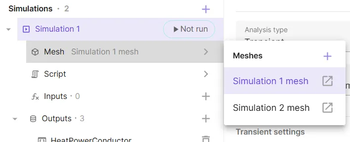
For more details on working with meshes, see the dedicated page Meshing.
Script
In Quanscient Allsolve, all user-set options in the GUI generate script files, which can be viewed and edited in the script view.
To open script view, click > next to Script:
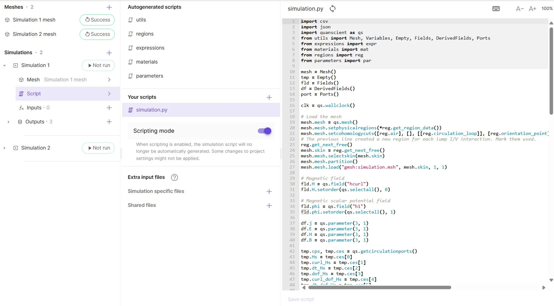
All regions, shared expressions and materials that are defined in the GUI are generated as Autogenerated scripts, and can be edited either in the script or through the GUI.
The base simulation script is autogenerated based on defined physics and simulation options in simulation.py.
The user has the flexibility to edit simulation.py script to their liking for advanced setups specific to their application.
To edit the scripts in your project, toggle on the Scripting mode.
For more details on working with scripts, see Scripting.
Inputs
There are 3 types of simulation inputs in Quanscient Allsolve:
- Sweeps
- Sweep over a shared expression with a vector of override values.
- Overrides
- Override a shared expression with a single value.
- Field initializations
- Use a stored field state from another simulation to initialize a field.
To create a new input for a simulation, click + next to Inputs:
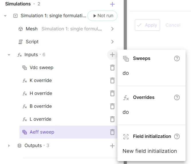
Next, we’ll take a closer look at each of the 3 input types.
Sweeps
Sweeps are an extension of overrides, and a sweep with a single value as the override expression is identical to an override. Only with sweeps, a vector of override values can be input as the override expression. In this case, a series of subsimulations is run in sequence for each value in the vector.
To define an override vector for a sweep, use the command linspace, or enter the elements of the vector within regular square brackets, [].
Below, an override vector is given for the Vdc sweep input, which sweeps over the shared expression Vdc.
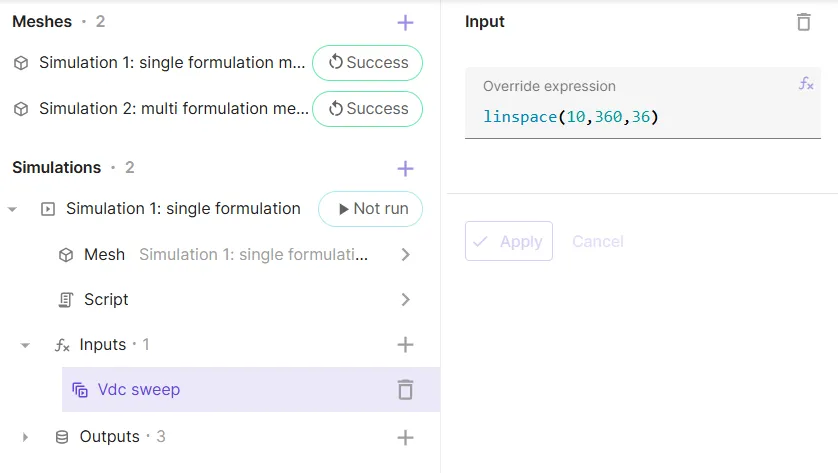
- The command
linspace(10, 360, 36)generates the vector[10, 20, 30, ..., 340, 350, 360]:- starting from
10 - ending at
360 36values
- starting from
- For further details about defining override vectors, see Using shared expressions for parametric sweeps.
With sweeps, you can easily run multiple variations of your model in one go, varying one or more parameters. Parameters to be swept over must be defined as shared expressions.
Overrides
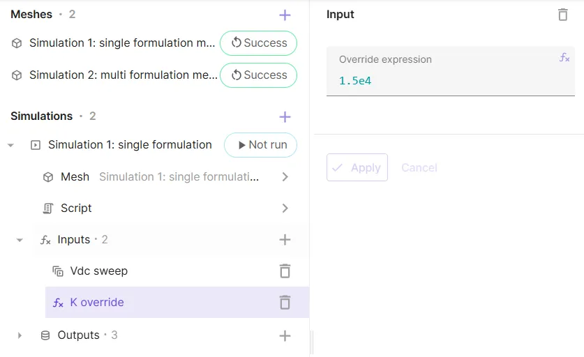
In some cases, you might want to modify the value of a shared expression only for the runtime of a specific simulation. Allsolve allows you to override a shared expression, changing the value temporarily for the runtime of a simulation.
To override a shared expression, add an override to simulation Inputs and define the override expression:
Field initializations
Outputs
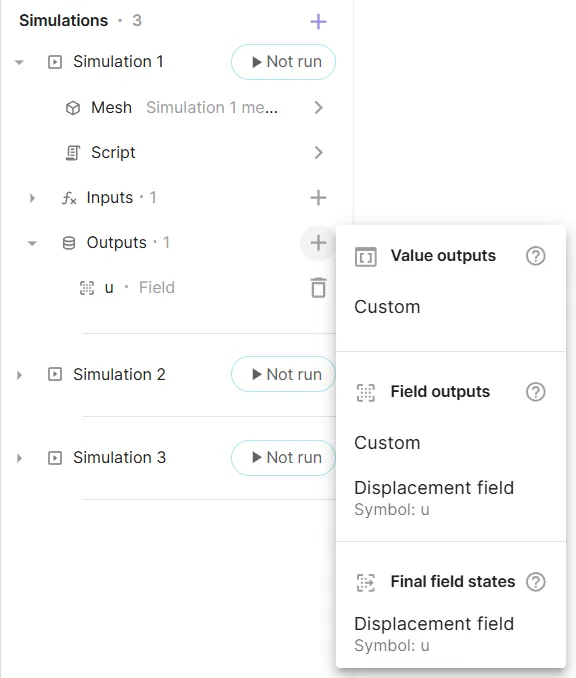
There are 3 types of simulation outputs in Quanscient Allsolve:
- Value outputs
- Outputs containing discrete value for each simulation and sweep step that can be plotted.
- Field outputs
- Outputs containing field states whose distribution over a domain can be visualized.
- Final field states
- Final field states stored at the end of a simulation, that can be used to initialize subsequent simulations.
To create a new output for a simulation, click + next to Outputs:
Next, we’ll take a closer look at each of the 3 output types.
Value outputs
Field outputs
Final field states
Results
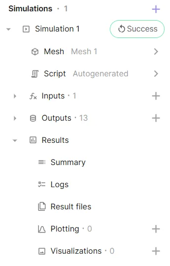
After a simulation has started running, Results can be accessed under the simulation.
In the simulation results, you can access:
- Summary
- See value outputs for each timestep or subsimulation.
- Logs
- See simulation status messages.
- Result files
- Download simulation results as
.vtuor.jsonfiles.
- Download simulation results as
- Plotting
- Plot value outputs.
- Visualizations
- Visualize field outputs.
Summary
In the Summary, you can keep track of all your value outputs. Value outputs are shown for each transient simulation timestep or sweep subsimulation.
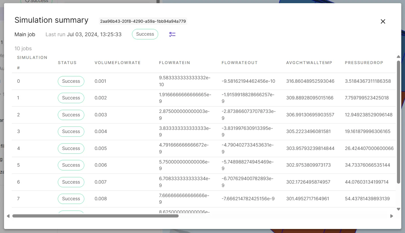
Also, if an error occurs and a simulation run fails, you can check the summary status column to see at what point it occurred.
Logs
Any status messages that are sent during simulation runs show up in the Logs. Taking a look at the simulation log is a good way to see what’s happening “under the hood” during simulation runs.
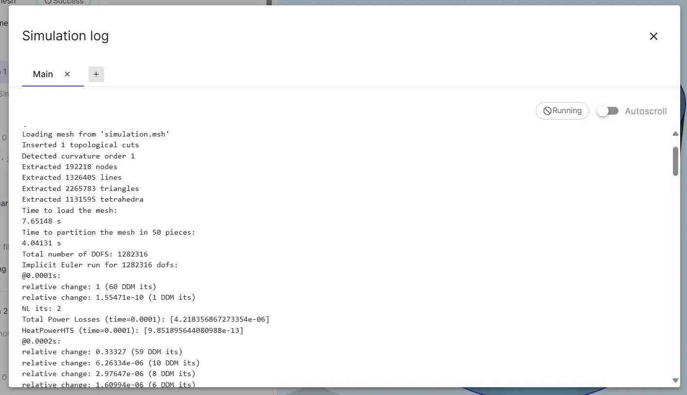
For a closer look at logs, see the dedicated section Simulation log.
Result files
Plotting
Visualizations
Simulation log
The simulation log in Quanscient Allsolve displays different things depending on the simulation. Different simulation data is displayed in the logs based on problem linearity, solver mode and analysis type, for example.
Nonlinear problem logs
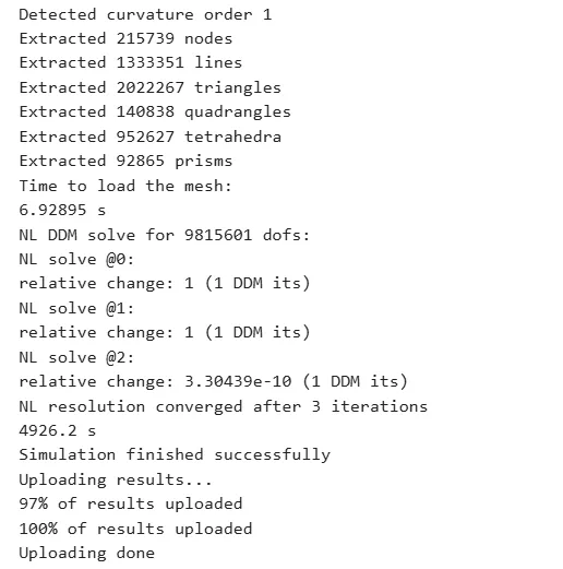
With nonlinear problems, the NL solve iterations and relative change between iterations is printed in the logs as below.
Direct solver logs
The simulation log for a simulation using the direct solver (non-DDM) displays some basic information about the simulation run, such as:
- general simulation phases
- mesh size
- mesh loading time
- solving time
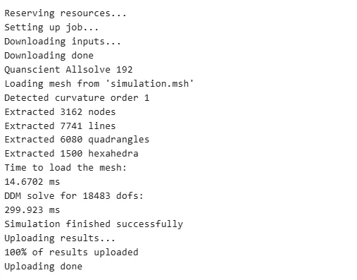
Direct solver solving time appears in the logs as
DDM solve for ___ dofs:___ mseven though DDM is not in use.
This is due to formulation.allsolve being a generic solver - it considers a non-DDM case as DDM with only one partition.
Iterative solver logs
The simulation log for a simulation using the iterative solver (DDM) displays the same basic information about the simulation run, as the with the direct solver:
- general simulation phases
- mesh size
- mesh loading time
- solving time
If more than one node is used, the mesh is partitioned between the nodes, and the pieces are solved in parallel. In this case, mesh partitioning and DDM solving data is shown in the logs as well:
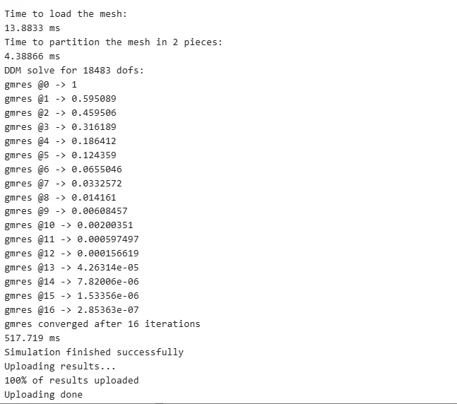
The abbreviation gmres stands for generalized minimal residual method (GMRES).
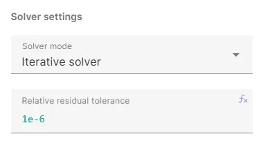
DDM is iterated until the Relative residual tolerance is subceeded.
In the example above, it was set as 1e-6:
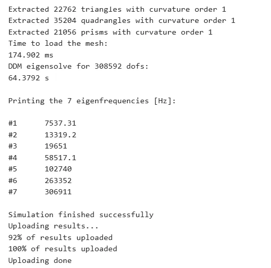
Eigenmode analysis logs
With the Eigenmode analysis type, eigenfrequencies are printed in the logs as below.
Sweep logs
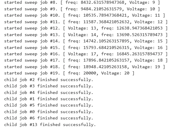
With sweep simulations, the status and successfulness of each subsimulation is printed in the logs as below.
