SC 002 - Quench - Hello World Demo
In this example, the quench event is simulated in a superconducting YBCO tape.
Model definition
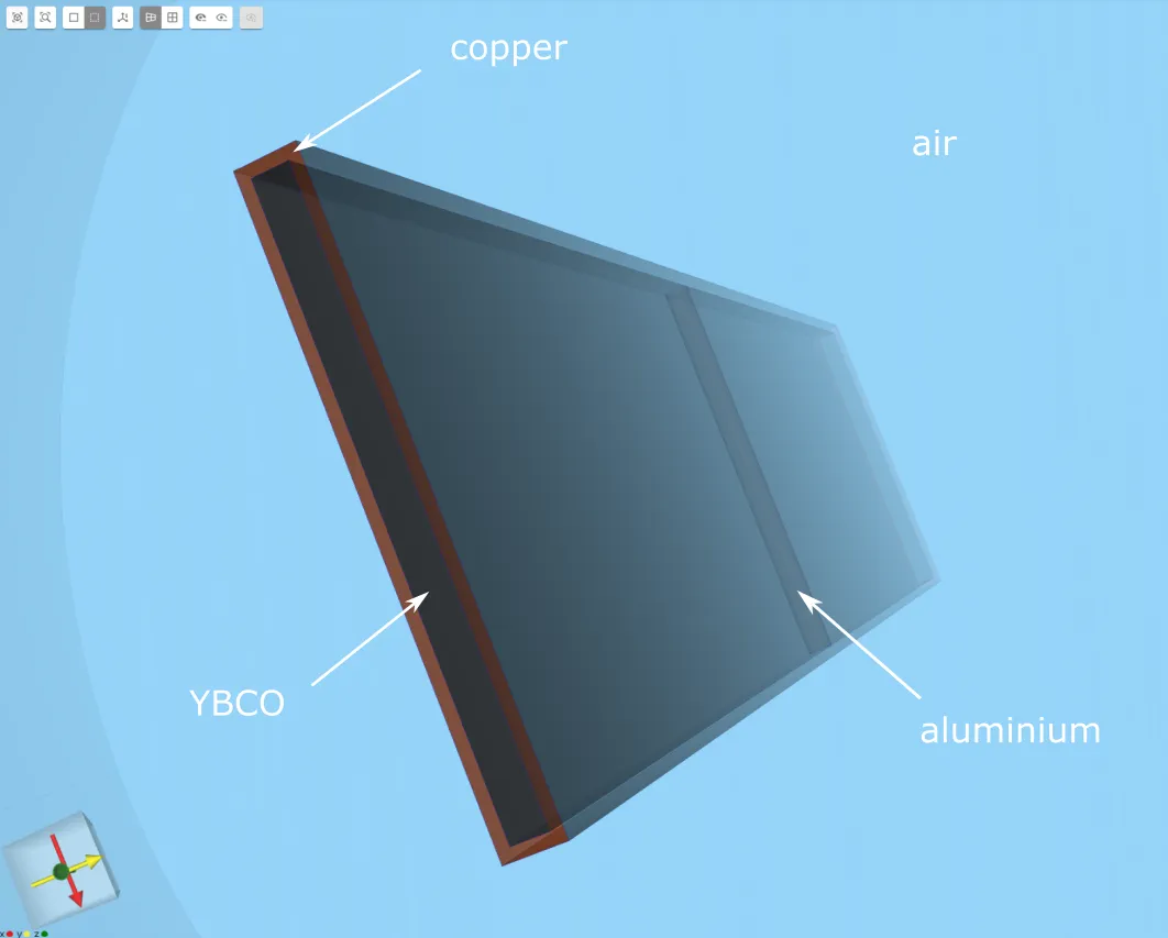
The tape model has a 0.8 mm YBCO core with a 0.2 mm copper coating.
To initiate quench, a high resistivity area is modeled in the YBCO core. This is done by adding an aluminium cylinder at the mid-section of the core.
| Element | XYZ dimensions [mm] | Aligned with axis |
|---|---|---|
| Copper box | 12 x 1.2 x 50 | Z |
| YBCO box | 11.6 x 0.8 x 50 | Z |
| Element | Radius [mm] | Height [mm] | aligned with axis |
|---|---|---|---|
| Air cylinder | 40 | 50 | Z |
| Aluminium cylinder | 0.4 | 11.6 | X |
The center point of each element listed here is at the origin, (0, 0, 0).
Simulation setup guide
Here, you’ll find a simplified guide on setting up this simulation in Quanscient Allsolve.
Step 1 - Create the geometry
In the Model section, build the copper box, YBCO box, air cylinder and aluminium cylinder as detailed in the Model definition.
Step 2 - Define materials and shared expressions
Proceed to the Properties section.
Assign the Copper, YBCO superconductor, Aluminium and Air materials to their corresponding volumes.
In this example, we need to make slight changes to the YBCO superconductor material properties.
- The predefined
YBCO_PowerLaw(j,T)function contains the constant current density termYBCO_Jc.- In a quench simulation, the current density must be a function of temperature, as the resistivity of the YBCO tape increases with temperature.
- Change the
YBCO_PowerLaw(j,T)function to use the current densityJcT(T)instead:
max(min(JcT(T)/YBCO_Ec * pow(norm(j)/JcT(T), 1.0-YBCO_n), 1e15), 1e6)- Define the function
JcT(T)as:
YBCO_Jc*ifpositive(T-Tc,1e-3,(Tc-T)/(Tc-Top))The constants YBCO_Jc, Tc and Top above are automatically defined.
Step 3 - Define the physics and apply boundary conditions
Proceed to the Physics section and add the following physics.
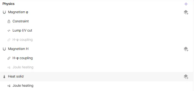
Under Magnetism φ, the Constraint target is a top edge point on the air cylinder. The Lump I/V cut target is a loop along the top outer edge of the copper box.
Under Magnetism H, H-φ coupling must be enabled.
Under Heat solid, the Joule heating target is the whole tape volume, with the copper box, YBCO box and aluminium cylinder included.
Step 4 - Set up the simulation, run and plot
Proceed to the Simulations section and add a mesh that suits your needs.
Add a new simulation and choose options. See step-by-step tutorial SC 001 - Superconductor AC loss for reference. Run the simulation.
Plot Time step in X axis and max T in YBCO in Y axis to see joule heating results.