MEMS 002 - PMUT
Model definition
In this example, a 6 x 6 array of PMUT (Piezoelectric micromachined ultrasonic transducers) is considered. Below is an image of the model geometry.
Simulation setup guide
Here, you’ll find a simplified guide on setting up this simulation in Quanscient Allsolve.
Step 0 - Define variables
In this example, it is useful to first define some variables, which will be used to create the geometry. The user can later edit the variables to try out different array sizes.
Start out in the Properties section by defining the following variables:
| Name | Expression | Description |
|---|---|---|
| freq | 1e6 | Frequency |
| R | 100e-6 | Cavity radius |
| thpiezo | 2e-6 | Piezo thickness |
| thcavity | 20e-6 | Cavity thickness |
| thmem | 10e-6 | Membrane thickness |
| n | 6 | Array size (even numbers only) |
| Rair | 5 * R * n | Air bubble radius |
Step 1 - Create the geometry
In the Model section, create the model geometry by creating geometry components as detailed below.
Create the components in the same order as listed.
- First, create a disc-shaped PMUT volume by creating 3 cylinders:
| Name | Component type | Geometric variable | Value |
|---|---|---|---|
| Membrane | Cylinder | Center point | (0, 0, 0) |
| Radius | R | ||
| Height | thmem | ||
| Rotation | (90, 0, 0) |
| Name | Component type | Geometric variable | Value |
|---|---|---|---|
| Piezo | Cylinder | Center point | (0, 0, thmem/2+thpiezo/2) |
| Radius | 0.67 * R | ||
| Height | thpiezo | ||
| Rotation | (90, 0, 0) |
| Name | Component type | Geometric variable | Value |
|---|---|---|---|
| Cavity | Cylinder | Center point | (0, 0, -thcavity/2-thmem/2) |
| Radius | R | ||
| Height | thcavity | ||
| Rotation | (90, 0, 0) |
- Then, use the Translation component 3 times to form a 6 x 6 grid of PMUT volumes:
| Name | Component type | Target volumes | Translation |
|---|---|---|---|
| translate | Translation | 1, 4, 7 | x: -4 * R * (n-1) / 2 |
| y: -4 * R * (n-1) / 2 | |||
| z: 0 |
| Name | Component type | Target volumes | Translation | Copy | Repeat count |
|---|---|---|---|---|---|
| translate 2 | Translation | 8, 9, 10 | x: 4 * R | Yes | n-1 |
| y: 0 | |||||
| z: 0 |
| Name | Component type | Target volumes | Translation | Copy | Repeat count |
|---|---|---|---|---|---|
| translate 3 | Translation | all volumes 8 - 25 | x: 0 | Yes | n-1 |
| y: 4 * R | |||||
| z: 0 |
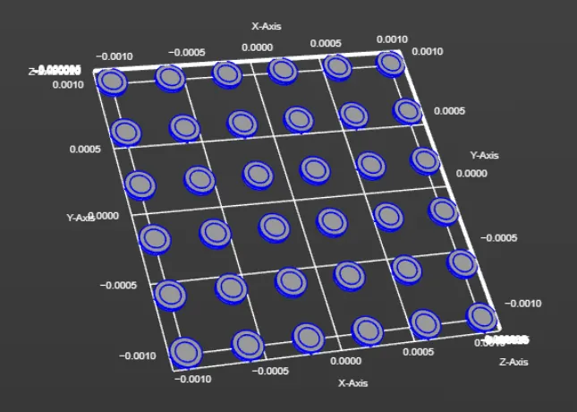
At this point, you should have a 6 x 6 grid like in the image below:
- Continue building the model by creating the following components:
| Name | Component type | Geometric variable | Value |
|---|---|---|---|
| sphere | Sphere | Center point | (0, 0, 0) |
| Radius | Rair |
| Name | Component type | Geometric variable | Value |
|---|---|---|---|
| box | Box | Center point | (0, 0, Rair+thmem/2) |
| Size | (2 * Rair, 2 * Rair, 2 * Rair) | ||
| Rotation | (0, 0, 0) |
| Name | Component type | Geometric variable | Value |
|---|---|---|---|
| box 2 | Box | Center point | (0, 0, Rair-thmem/2-thcavity) |
| Size | (2 * Rair, 2 * Rair, 2 * Rair) | ||
| Rotation | (0, 0, 0) |
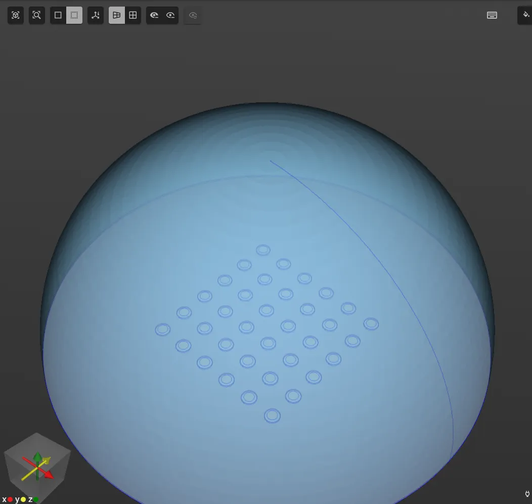
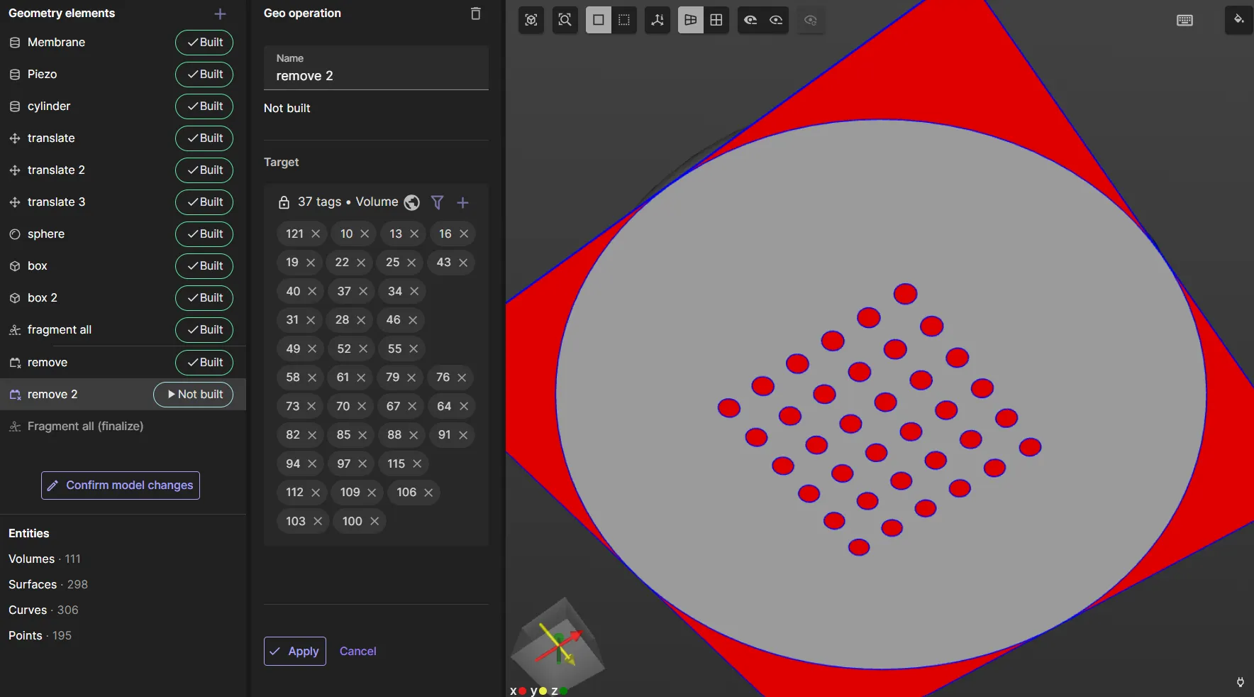
- Then, apply the
fragment alloperation. At this point, the model should look like in the image below (in translucent mode):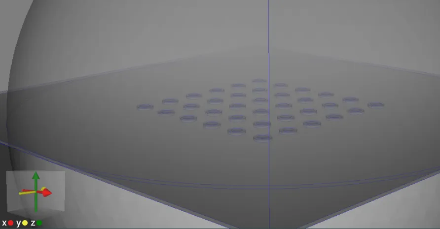
- Finally, apply the
removeoperation in two steps to remove extra volumes. First, remove the bottom half of the sphere, as well the box and the thin box layer on top of it.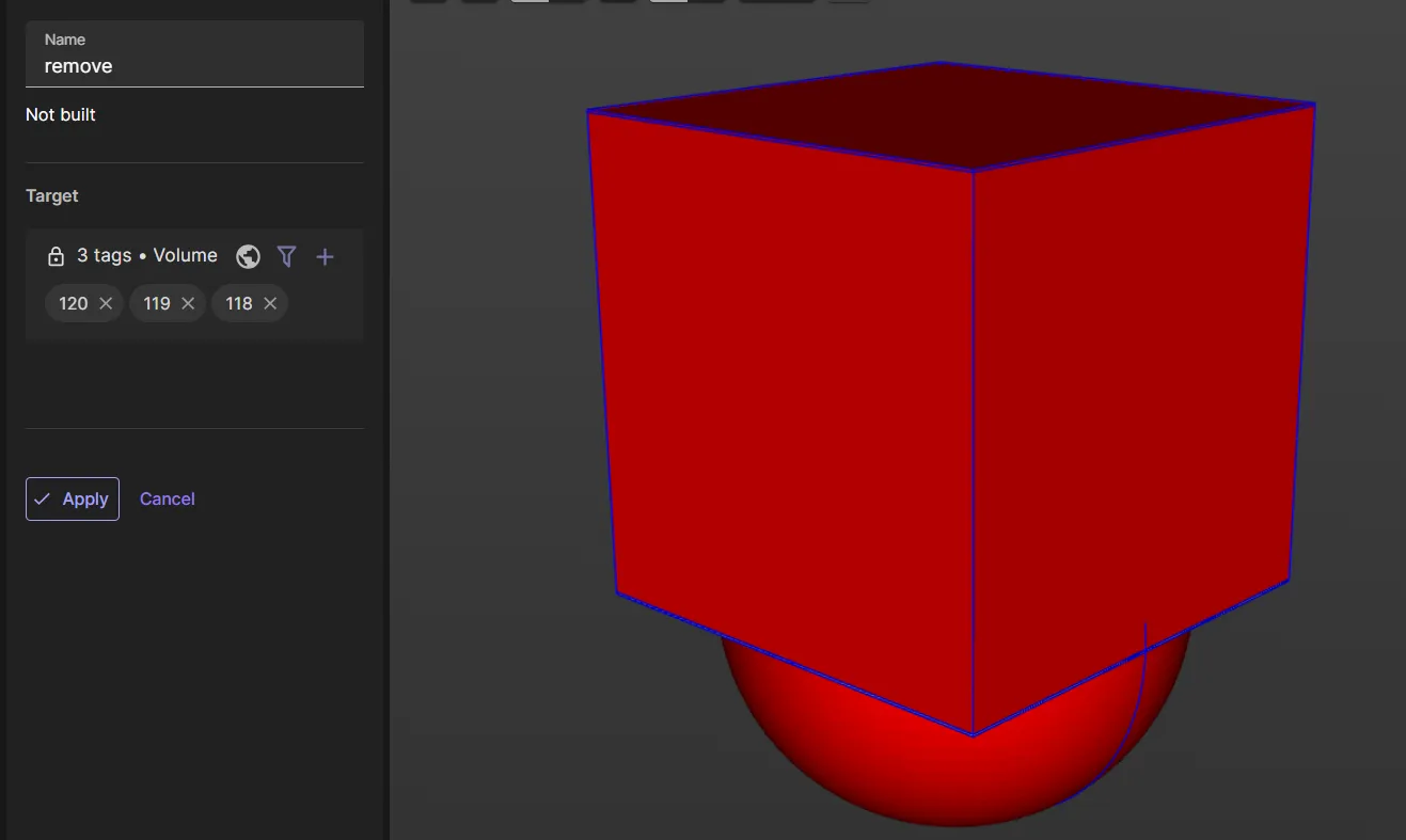 Then, remove the extra box section along the outer egde of the circular baseplate, as well as the cavity discs under each PMUT.
Now, your model is finished.
Step 2 - Define the materials
Proceed to the Properties section to define the model materials.
Pick the Air material from the materials database and assign it to the air bubble volume. Save the target as a shared region.
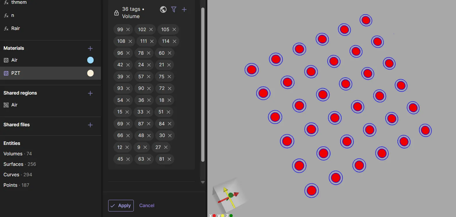
Next, pick the PZT material from the materials database. As the target, select all of the small top discs of the PMUTs.
Save the target as a shared region.
Finally, pick the Monocrystalline silicon material from the materials database. As the target, select all the leftover volumes, i.e. the membranes of all PMUTs as well as the large circular baseplate. Save the target as a shared region.
Now, your model materials are defined.
Step 3 - Define the physics
Proceed to the Physics section to define the physics.
For PMUT simulations, Elastic waves, Acoustic waves and Electrostatics physics are required.
Step 3 has some outdated notation. Also tags might be wrong.
- Under Elastic waves, add
ClampandPiezoelectricity.
- As elastic waves target, set all volumes except the air bubble.
- As clamp target, set the baseplate (volume
117). - As piezoelectricity target, select the shared region
PZT target.
- Under Acoustic waves, add
Perfectly matched layerandAcoustic structure.
- As acoustic waves target, set the air bubble (volume
116). - As perfectly matched layer target, set the air bubble surface (surface
655).
- Under Electrostatics, add
ConstraintandLump V/Q.
- As electrostatics target, select the shared region
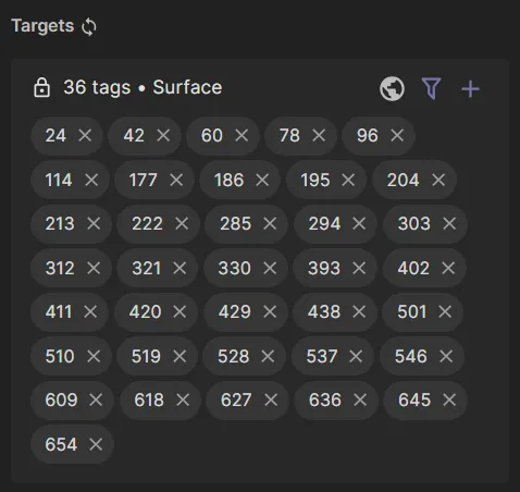
PZT target. - As constraint target, set a specific inner surface of each PMUT.
The desired target surface tags are in the image below:
- Set the constraint value to
0. - As lump V/Q target, set the top surface of the PZT disc of each PMUT.
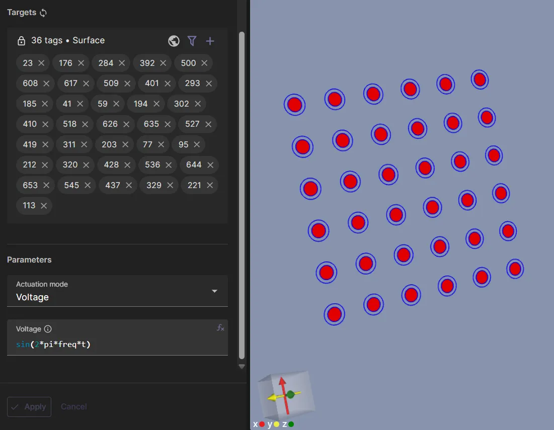
- Set the lump V/Q voltage to
sin(2*pi*freq*t).
Now, your simulation physics are defined.
Step 4 - Set up the mesh
Proceed to the Simulations section to set up the mesh:
- Create a new mesh with
Mesh qualityset toExpert settings. - Set Max size to
1e-4. - Click
Apply & mesh.
Step 5 - Simulate
In the Simulations section, create a new simulation with the following options:
- Set Analysis type to
Harmonic. - Set Fundamental frequency to
freq. - Set Number of FFt samples to
3. - Set Node count to
10. - Set Node type to
1 CPU, 16 GB. - As the Mesh, select the mesh you created.
- To Input, add
freq sweep.- Set Override expression to
linspace(0.7e6, 0.9e6, 41).
- Set Override expression to
- To Output, add:
u harmonic 2field- Skin only
p harmonic 2field- Skin only
P abovecustom value output.- Output expression:
probe(reg.p_above, sqrt(pow(harm(2, p), 2) + pow(harm(3, p), 2))) - Here
reg.p_aboverefers to a shared region point with tag438and nameP above.
- Output expression:
Run the simulation by clicking Not Run.
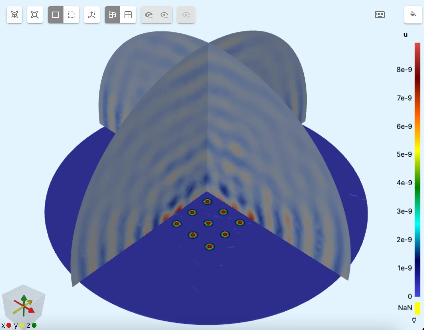
Step 6 - Visualize
In the Simulations section, add visualizations and plots as needed. A visualization example is in the image below.