MEMS 003 - CMUT ultrasound send / receive
Model definition
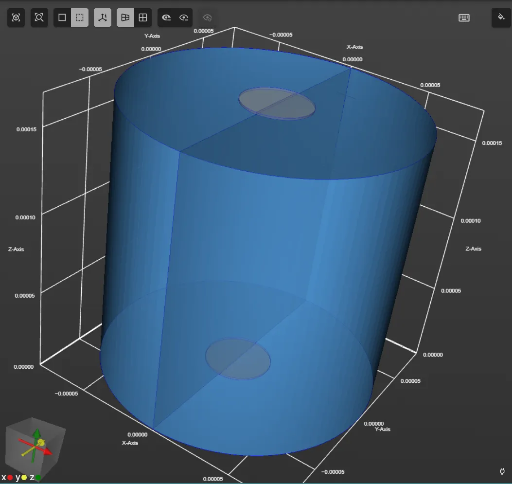
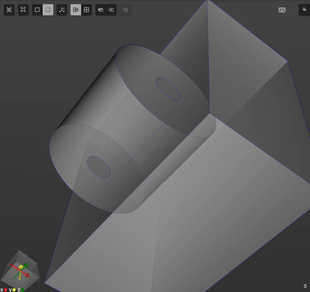
In this example, a model with two CMUT (Capacitive micromachined ultrasonic transducers) facing each other is considered. One of the CMUTs is an emitter and the other is a receiver. Between them, a volume of water is modeled as a medium. Below is an image of the model geometry.
Simulation setup guide
Here, you’ll find a simplified guide on setting up this simulation in Quanscient Allsolve.
Step 0 - Define shared expressions
In this example, it is useful to first define some shared expressions. These shared expressions will then be used to create the geometry. In addition, the shared expressions can later be edited to easily modify the geometry.
Start out in the Properties section by defining the following shared expressions:
| Name | Description | Expression |
|---|---|---|
| thmem | Membrane thickness | 1e-6 |
| radmem | Membrane radius | 20e-6 |
| cmutdist | Distance between emitter and receiver CMUT | 0.5e-3/3 |
| thgap | Vacuum gap thickness | 200e-9 |
| VDC | Direct current voltage | 50 |
| freq | AC signal frequency | 10e6 |
| VAC | Alternating current voltage | 2*sin(2*pi*freq/2*t)*sin(2*pi*freq/2*t) |
Step 1 - Create the geometry
In the Model section, create the model geometry by creating geometry elements as detailed below.
Create the elements in the same order as listed.
- First, create cylinders for the top and bottom CMUT, as well as the water medium:
| Name | Element type | Geometric variable | Value |
|---|---|---|---|
| membranebot | Cylinder | Center point, (x, y, z) | (0, 0, 0) |
| Radius | radmem | ||
| Height | thmem | ||
| Rotation, (x, y, z) | (90, 0, 0) |
| Name | Element type | Geometric variable | Value |
|---|---|---|---|
| vacuumgapbot | Cylinder | Center point, (x, y, z) | (0, 0, -thgap/2-thmem/2) |
| Radius | radmem | ||
| Height | thgap | ||
| Rotation, (x, y, z) | (90, 0, 0) |
| Name | Element type | Geometric variable | Value |
|---|---|---|---|
| water | Cylinder | Center point, (x, y, z) | (0, 0, cmutdist/2+thmem/2) |
| Radius | cmutdist/2 | ||
| Height | cmutdist | ||
| Rotation, (x, y, z) | (90, 0, 0) |
| Name | Element type | Geometric variable | Value |
|---|---|---|---|
| membranetop | Cylinder | Center point, (x, y, z) | (0, 0, cmutdist+thmem) |
| Radius | radmem | ||
| Height | thmem | ||
| Rotation, (x, y, z) | (90, 0, 0) |
| Name | Element type | Geometric variable | Value |
|---|---|---|---|
| vacuumgaptop | Cylinder | Center point, (x, y, z) | (0, 0, cmutdist+thmem+thgap/2+thmem/2) |
| Radius | radmem | ||
| Height | thgap | ||
| Rotation, (x, y, z) | (90, 0, 0) |
- Then, create a box that divides the cylinders along the Y-axis:
| Name | Element type | Geometric variable | Value |
|---|---|---|---|
| box | Box | Center point, (x, y, z) | (cmutdist/2, 0, cmutdist/2) |
| Size, (x, y, z) | (cmutdist, 2*cmutdist, 2*cmutdist) | ||
| Rotation, (x, y, z) | (0, 0, 0) |
At this point, your model should look like in the image below:
- Next, use the
fragment alloperation. Now, all the cylinders should be split into 2 volumes along the Y-axis.
- Then, use the
removeoperation to remove the unnecessary box (tag11). Now, your model geometry is finished.
Step 2 - Define the materials
Proceed to the Properties section to define the materials.
Pick the Water material from the materials database and assign it to both halves of the water cylinder (volumes 5 and 6). Save the target as a shared region.
Next, pick the Monocrystalline silicon material from the materials database. As the target, select volumes 1, 2, 7 and 8.
Save the target as a shared region.
image
Finally, pick the Vacuum material from the materials database. As the target, select volumes 3, 4, 9 and 10. Save the target as a shared region.
Now, your model materials are defined.
Step 3 - Define the physics
Proceed to the Physics section to define the physics.
For this CMUT simulation, Solid mechanics, Electrostatics and Acoustic waves physics are required.
1 - Solid mechanics:
- As solid mechanics target, select the shared region
Monocrystalline silicon target. - Add
Clamp.- As clamp target, select surfaces
1,5,22and25.
- As clamp target, select surfaces
2 - Electrostatics:
- As electrostatics target, select volumes
1-4and7-10. - Add
Constraint, and name it asGround.- As target, set surfaces
10,12,29and31. - Set constraint value to
0.
- As target, set surfaces
- Add
Constraint, and name it asSignal.- As target, set surfaces
4and6. - Set constraint value to
VDC+VAC.
- As target, set surfaces
- Add
Lump V/Q.- As lump V/Q target, set surfaces
17and21. - Set Voltage to
VDC.
- As lump V/Q target, set surfaces
3 - Acoustic waves:
- As acoustic waves target, select the water volumes (tags
5and6). - Add
Perfectly matched layer.- As target, set surfaces
13and18.
- As target, set surfaces
- Add the
Acoustic structuresolid mechanics coupling.
Now, your simulation physics are defined.
Step 4 - Set up the mesh
Proceed to the Simulations section and create a new mesh:
- Set Mesh quality to
Expert settings. - Set Max size to
1e-5. - Click
Apply & mesh.
Step 5 - Simulate
In the Simulations section, create a new simulation with the following options:
- Set Analysis type to
Transient. - Set Timestep algorithm to
Generalized alpha. - Set Start time to
0. - Set End time to
5e-7. - Set Timestep size to
1e-8. - Set Solver mode to
Iterative solver.- Set Relative residual tolerance to
1e-6.
- Set Relative residual tolerance to
- Set Node type as
4 CPU, 64 GB. - As the Mesh, select the mesh you created.
- In Output:
- Add
pressure field p. - Add custom value output with name
Capacitance measured.- Output expression:
lump.Q/lump.V.
- Output expression:
- Add
Run the simulation by clicking Not Run.
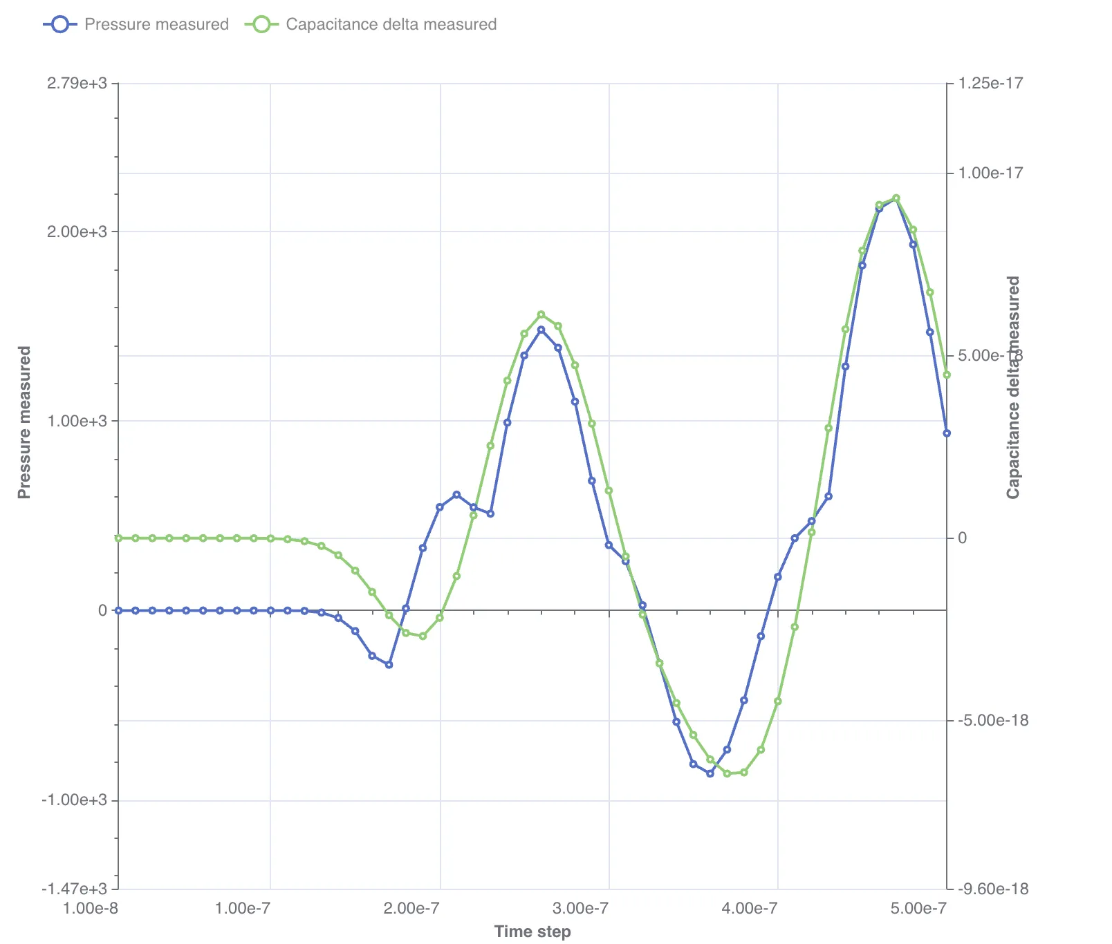
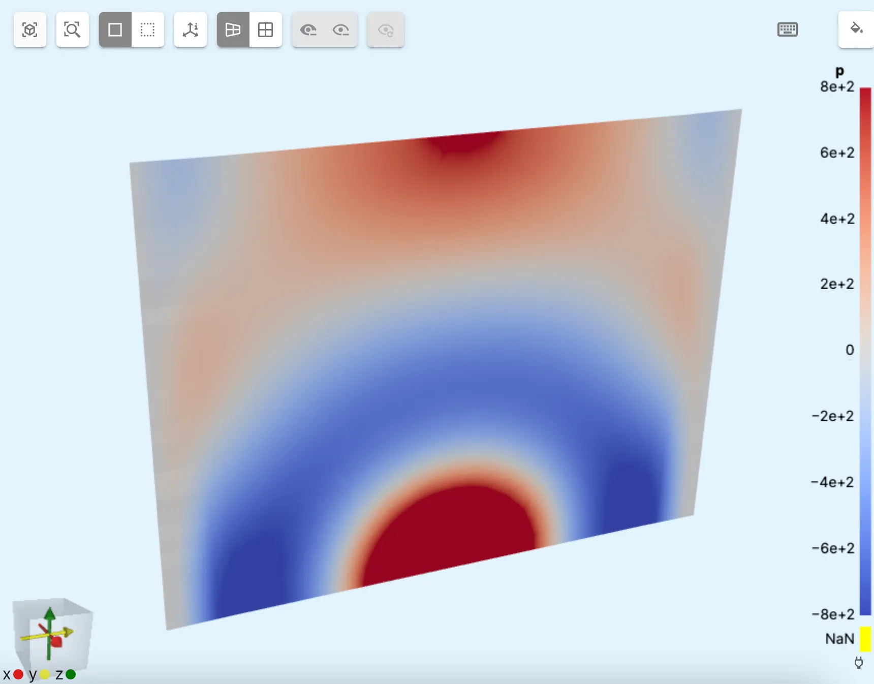
Step 6 - Visualize
In the Simulations section, add plots and visualizations to see results.
An example plot and visualization are in the images below: