Coaxial tee S-parameters - RF 004
Prerequisites: complete RF 001 — Eigenmode ports and S-parameters first — it introduces eigenmode ports, S-parameters, and the harmonic sweep workflow used here.
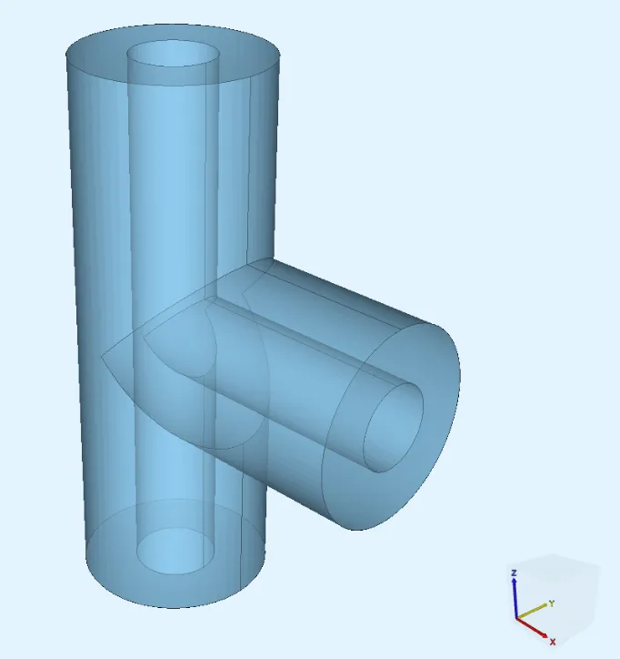
A coaxial tee is a three-port power splitter formed by joining a branch coaxial line at a right angle to the midpoint of a main coaxial line. Power entering any port splits between the other two. The geometry dimensions give a characteristic impedance on every arm.
This tutorial reproduces the coaxial tee benchmark from ANSYS HFSS Getting Started Workshop 4.1 1 and compares S-parameter results across the 1–10 GHz band.
Simulation setup guide
Section titled “Simulation setup guide”Step 1 - Import variables
Section titled “Step 1 - Import variables”In the Common sidebar, open the Variables panel, and import the following variables as CSV:
Name,Expression,Descriptionouter_r,0.00189,Outer conductor inner radius [m]pin_r,0.000821,Inner conductor (pin) radius [m]main_len,0.0108,Main arm total length [m]branch_len,0.0054,Branch arm length [m]tol,1e-4,Region-selection tolerance [m]freq,1000000000.0,Operating frequency [Hz]| Name | Description | Expression |
|---|---|---|
| outer_r | Outer conductor inner radius [m] | 0.00189 |
| pin_r | Inner conductor (pin) radius [m] | 0.000821 |
| main_len | Main arm total length [m] | 0.0108 |
| branch_len | Branch arm length [m] | 0.0054 |
| tol | Region-selection tolerance [m] | 1e-4 |
| freq | Operating frequency [Hz] | 1000000000.0 |
Step 2 - Build the geometry
Section titled “Step 2 - Build the geometry”Go to the Geometry section. Build the coaxial tee from four cylinders and three boolean operations.
-
Add a new Cylinder named
main_outer:Setting Value Radius outer_rHeight main_len -
Copy
main_outerand edit the copy:Setting Value Name main_pinRadius pin_r -
Add a new Cylinder named
branch_outer:Setting Value Center X branch_len / 2Radius outer_rHeight branch_lenRotation Y 90 -
Copy
branch_outerand edit the copy:Setting Value Name branch_pinRadius pin_r -
Add a Union operation named
outer_union:Setting Value Set / main_outer,/ branch_outer -
Add a Union operation named
pin_union:Setting Value Set / main_pin,/ branch_pin -
Add a Difference operation named
air_domain:Setting Value Set 1 / outer_unionSet 2 / pin_unionDelete Yes -
Select
Confirm model changes.
Step 3 - Create regions
Section titled “Step 3 - Create regions”Return to the Common sidebar and open the Regions panel. Create the following regions:
-
Add a volume region named
air_volumetargeting the entire air domain volume. -
Add a surface region named
port1targeting the main cylinder bottom surface (Z-min face). -
Add a surface region named
port2targeting the branch cylinder end surface (X-max face). -
Add a surface region named
port3targeting the main cylinder top surface (Z-max face). -
Add a surface region named
all_surfacestargeting all surfaces of the air domain. -
Add a computed surface region named
pec_walls:Setting Value Operation Difference A all_surfacesB port1,port2,port3This selects all outer walls except the three port faces.
Step 4 - Apply materials
Section titled “Step 4 - Apply materials”Go to the Physics section. Assign the Air material from the library to the air_volume region.
Step 5 - Define the physics
Section titled “Step 5 - Define the physics”In the Physics section, add the Electromagnetic waves physics.
-
Add a Perfect conductor interaction:
Setting Value Name PEC wallsTarget pec_walls -
Add an Eigenmode port interaction:
Setting Value Name Port 1Target port1Number of eigenmodes to find 5Eigenmode index 0Target eigenvalue Effective refractive index Effective refractive index 1Drive Yes Driving signal sin(2*pi*freq*t) -
Copy
Port 1and edit the copy:Setting Value Name Port 2Target port2 -
Copy
Port 2and edit the copy:Setting Value Name Port 3Target port3
Step 6 - Generate the mesh
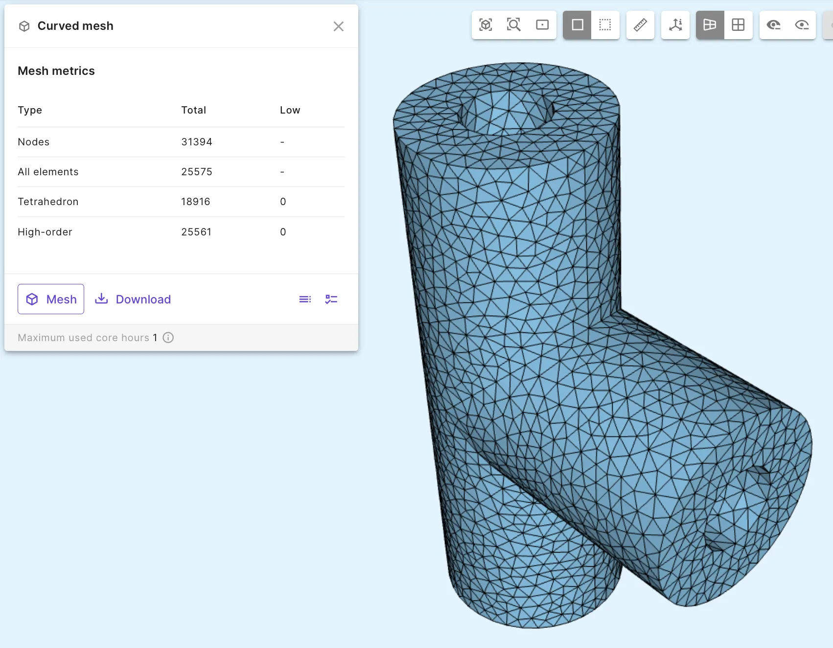
Section titled “Step 6 - Generate the mesh”Go to the Simulations section and create a new mesh named curved mesh. Configure the following settings:
| Setting | Value |
|---|---|
| Mesh element size | Absolute |
| Min. size | 0.0001 |
| Max. size | 0.0005 |
| Curvature enhancement | 0.2 |
| Curved mesh | Yes |
Step 7 - Set up and run the simulation
Section titled “Step 7 - Set up and run the simulation”In the Simulations section, add a new simulation:
| Setting | Value |
|---|---|
| Name | Coax Tee S-Parameters |
| Description | Harmonic EM simulation — S-parameters and E-field |
| Analysis type | Harmonic |
| Fundamental frequency | freq |
| Number of FFT samples | 3 |
| Solver mode | Iterative solver |
| Mesh | curved mesh |
Inputs:
- In the Common sidebar, add a variable override for
freq. - Set the override expression to
linspace(1e9, 1e10, 10). - Add this override as an input to the simulation.
Outputs:
- Add
S-parameters. - Add
Electric field(2nd harmonic).- Rename to
E-field. - Turn on
Skin only.
- Rename to
Run the simulation.
Step 8 - Results
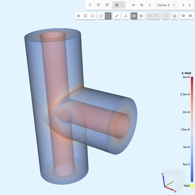
Section titled “Step 8 - Results”After the simulation completes, add a visualization for the E-field output and browse through sweep steps:
Plot the S-parameters to see the frequency-dependent power split:
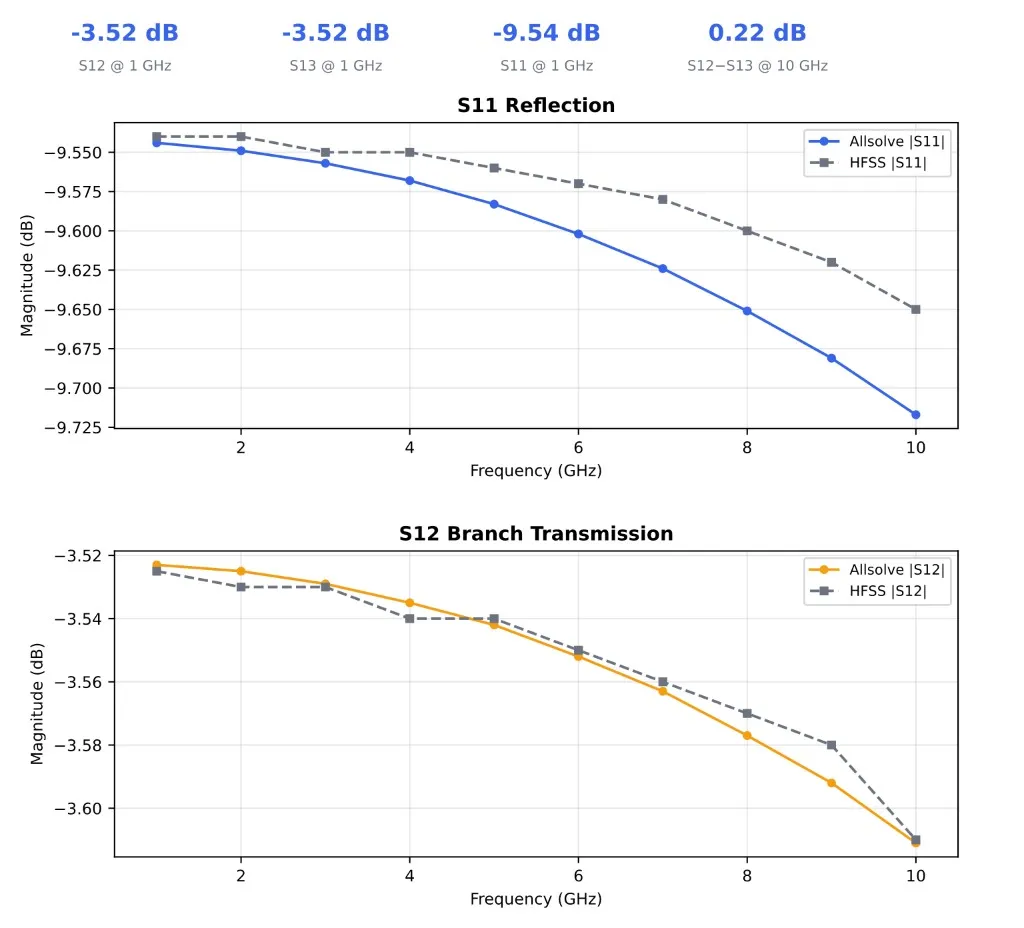
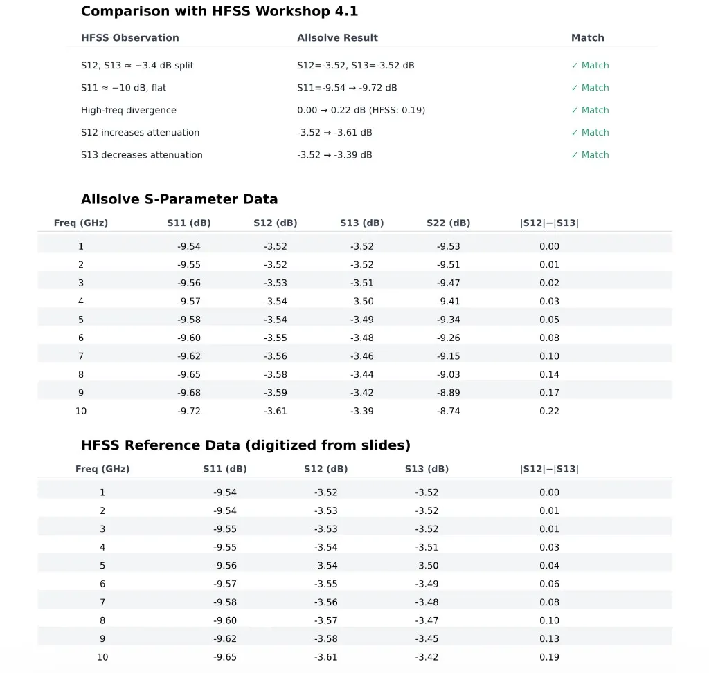
- S11 (reflection): approximately −9.5 dB, nearly flat across the band.
- S12 (branch transmission): approximately −3.5 dB at 1 GHz, decreasing slightly at higher frequencies.
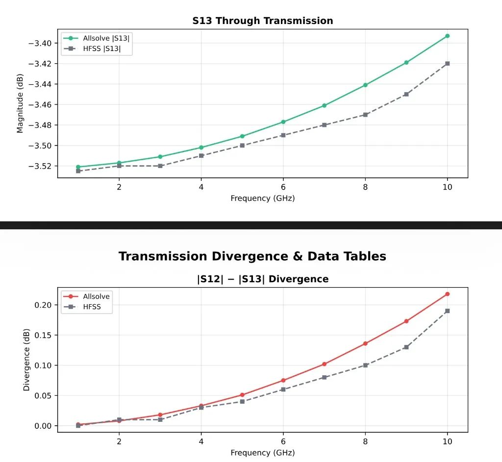
- S13 (through transmission): approximately −3.5 dB at 1 GHz, increasing slightly at higher frequencies.
Results comparison
Section titled “Results comparison”See the following plots for results comparison with ANSYS HFSS2.