
Working with geometries
Geometry editing in Quanscient Allsolve is done in the Geometry section. The Geometry elements list is at the top of the Navigation panel (left sidebar). Geometric Entities are in the Common sidebar on the right. For imported CAD with assembly structure, an Assemblies tree shows the hierarchical part names from the file. See Assemblies.
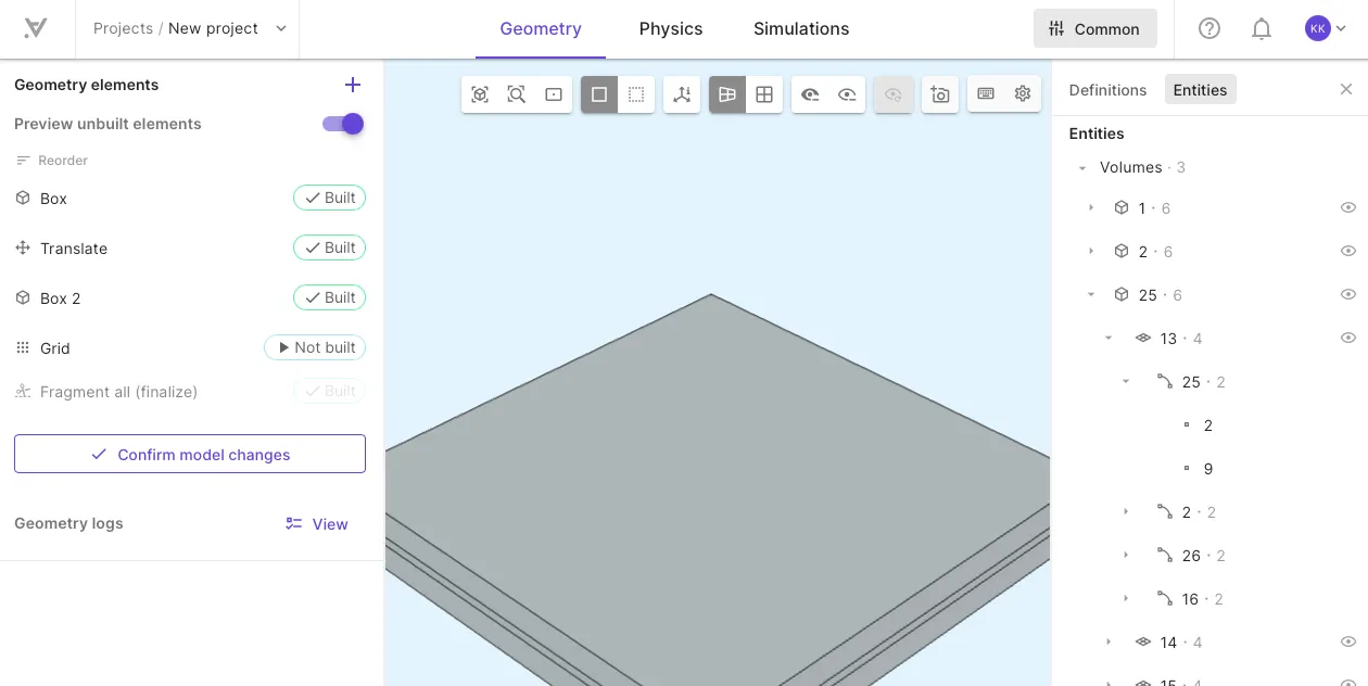
Geometry elements
Section titled “Geometry elements”All shapes, imports and operations are referred to commonly as Geometry elements.
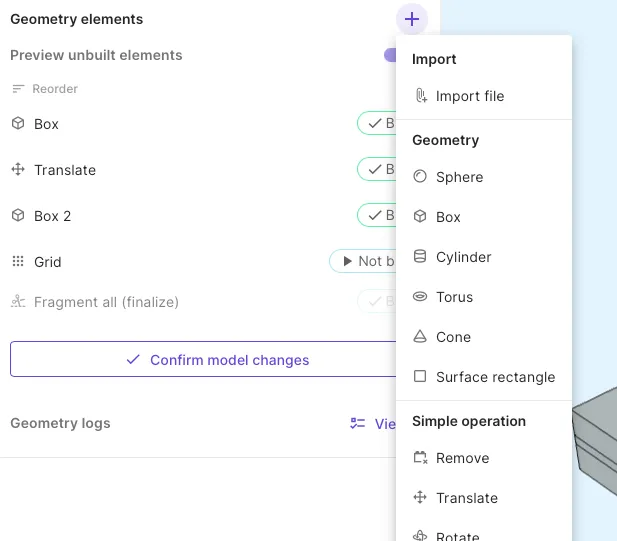
- Import
- Import file - Import CAD or mesh files
.step.iges.brep.gds.msh.nas
- Import file - Import CAD or mesh files
- Shapes
- Sphere
- Box
- Cylinder
- Torus
- Cone
- Surface rectangle - Useful for defining port surfaces
- Simple operations
- Remove - Remove volumes.
- Translate - Move selected volume or create copies.
- Rotate - Rotate selected volume around an axis or create rotated copies.
- Grid - Copy a volume along one or more axes to form a grid.
- Boolean operations (see Boolean operations)
- Fragment all - Run automatic Fragments operation on all volumes against all.
- Intersection - Portion common to all selected volumes is kept.
- Union - Merge all selected volumes/surfaces.
- Difference - Subtracts volume set 2 from volume set 1.
- Fragments - Split overlapping volumes into new, non-overlapping volumes.
Building elements
Section titled “Building elements”To add elements:
- If geometry editing is inactive, select
Edit model. - Select
+next to Geometry elements. - Select a shape or operation.
- Adjust element properties/settings.
Saveyour settings.- Reorder if necessary and build the elements.
- Select
Confirm model changesto finalize. The model is updated and entity tags are locked.
Element ordering
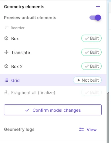
Section titled “Element ordering”Geometry elements work as a stack where each new element is built on top of previous ones. The list ordering goes from top to bottom - the newest element is always at the bottom of the list.
Enabling and disabling elements
Section titled “Enabling and disabling elements”Every geometry element has an Enabled setting that controls whether it contributes to the model when built. Turn an element off to exclude it without deleting it — useful for comparing design variants or temporarily removing a feature while you work on the rest of the model.
Geometric sweeps
Section titled “Geometric sweeps”Enabled also accepts an expression, so you can drive it from a variable. Use variables to switch parts of the geometry on and off parametrically, or sweep over alternative versions of your geometry.
To set up a geometric sweep:
-
Open geometry element settings.
-
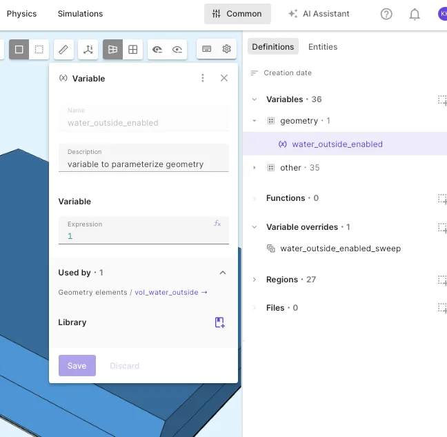
Next to the Enabled toggle, select and enter a variable such as
water_outside_enabledin the expression field.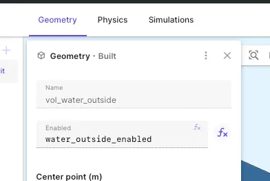
-
Create a Sweep override with values
1(enabled) and0(disabled).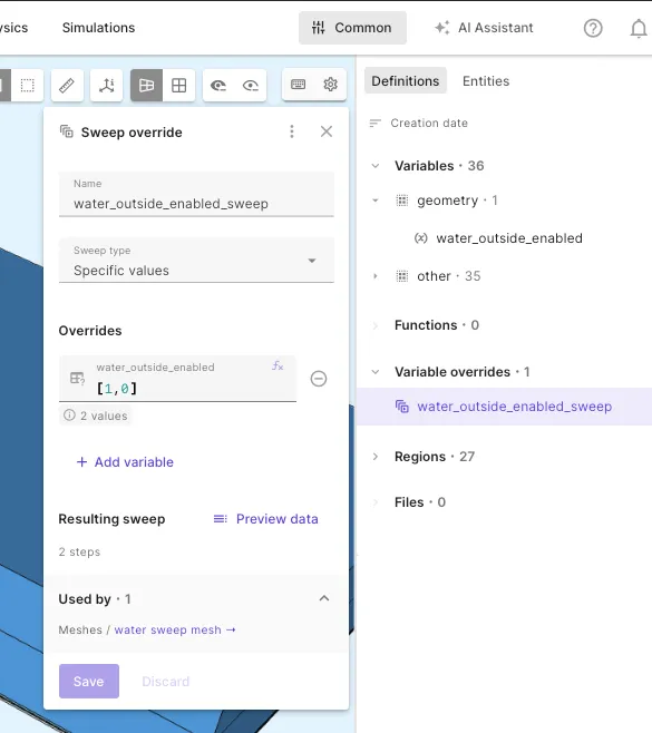
-
Create a mesh with the sweep override so that it has an instance for each version of the geometry.
-
Add the mesh and sweep override to your simulation to simulate for each version of the geometry.
Setting up a geometric sweep follows the same steps as sweeping over enabled/disabled materials or physics interactions, except for meshing - you must make a mesh with your override to have a mesh instance for each version of the geometry.
Referencing entities by name
Section titled “Referencing entities by name”Operations such as Remove, Translate, Rotate, and the boolean operations act on a set of target entities. The recommended way to select targets is by name based on Attribute rule selector logic.
Targets can also be selected directly on the model view or by picking integer tags.
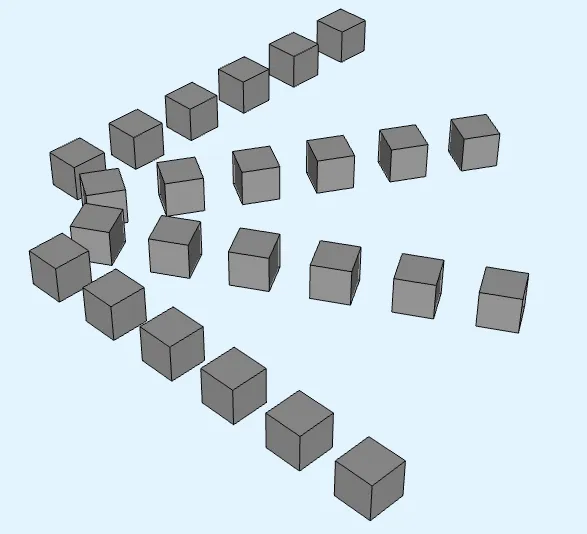
Translate and rotate: copying
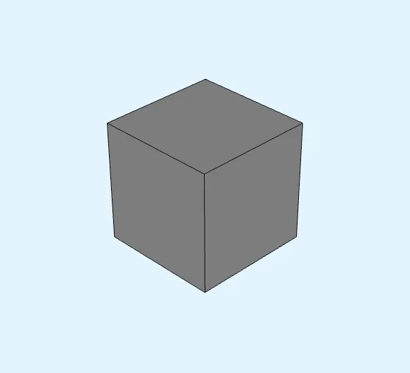
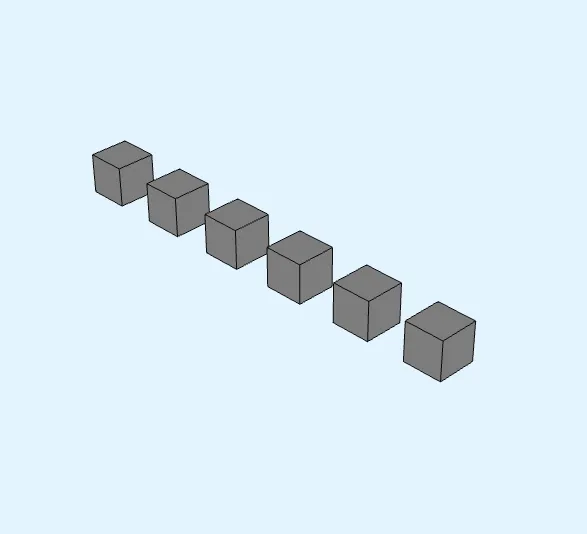
Section titled “Translate and rotate: copying”The translate and rotate operations support copying. Enable copying in the operation settings and set the number of copies to create. Each copy is translated or rotated by the specified amount relative to the original.
| Original box | Translate with 5 copies | Rotate with 3 copies |
|---|---|---|
 |
 |
 |
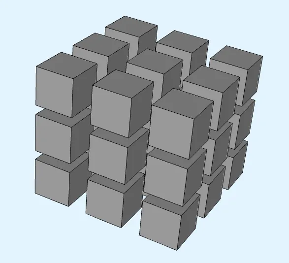
Use the grid operation to create a 2- or 3-dimensional grid from the selected volume/volumes. The grid operation can also copy a volume along a single axis, just like the translate operation.
Boolean operations
Section titled “Boolean operations”Boolean operations combine or subtract volumes (and surfaces in 2D) to build shapes that simple primitives cannot describe on their own. Populate each operation’s volume set by selecting target entities — prefer selecting by name so the operation survives pipeline changes.
| Operation | Volume sets | Result |
|---|---|---|
| Union | One | Merges all selected volumes/surfaces into a single entity. |
| Intersection | One | Keeps only the region shared by all selected volumes; discards the rest. |
| Difference | Two | Subtracts volume set 2 from volume set 1. |
| Fragments | One | Splits overlapping volumes along their shared boundaries into new, non-overlapping volumes. |
| Fragment all | — | Runs Fragments on every volume against every other volume in the model. |
Fragments and Fragment all do not add or remove material — they only split existing volumes so that neighbouring parts share conforming boundaries, which is required for the mesh to connect adjacent regions.