
Piezocomposite array with backing and matching
Prerequisites: complete the Piezocomposite transducer tutorial first. It covers the basic geometry, piezoelectricity coupling, and Lump V/Q excitation workflow.
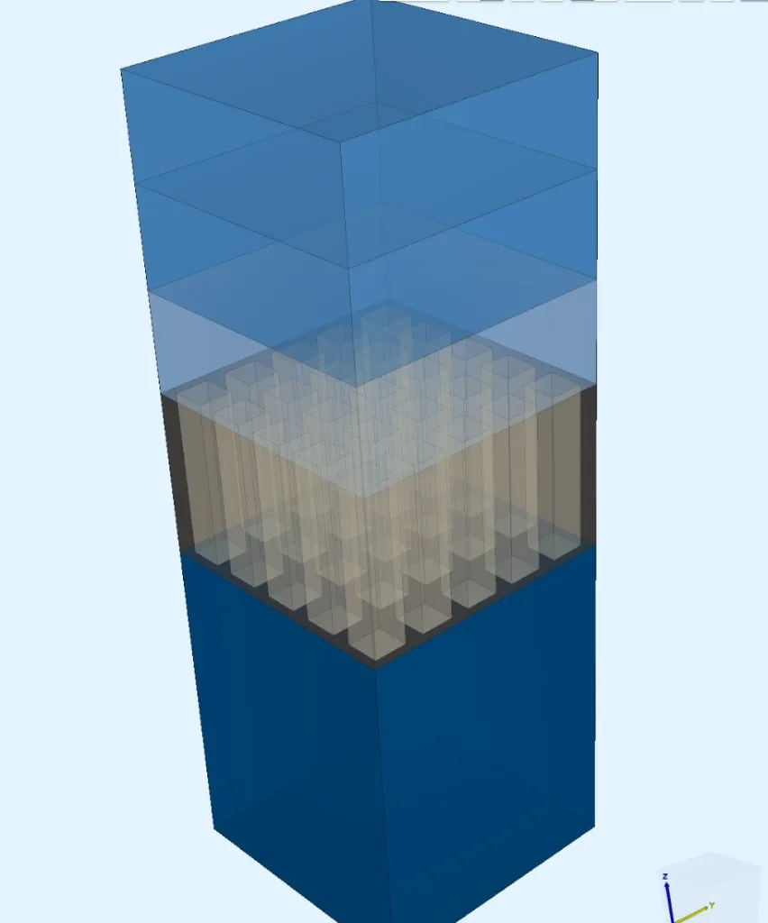
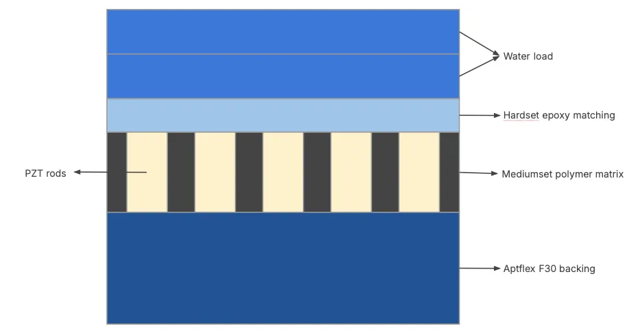
This tutorial models a 5×5 piezocomposite transducer array with backing and matching layers. The centre element is driven with a voltage wavelet, and the simulation produces:
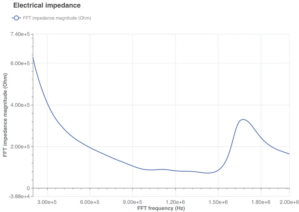
- Electrical impedance Z(f) via FFT
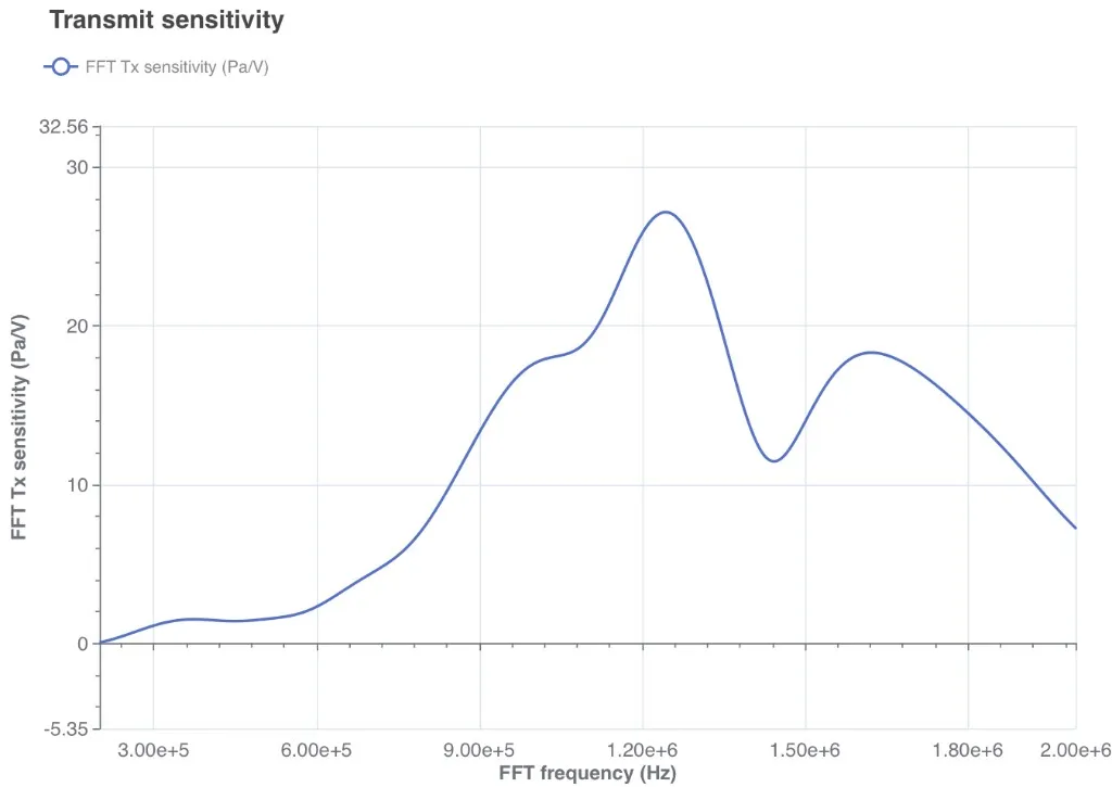
- Front-face and far-field transmit sensitivity (Pa/V)
- Beam pattern via Kirchhoff-Helmholtz extrapolation
Demo project: 1-3 Piezocomposite array
Simulation setup guide
Section titled “Simulation setup guide”Step 1 — Variables
Section titled “Step 1 — Variables”Create a new project and start without geometry. Open the Common sidebar, Definitions tab, and import the following variables via Import CSV:
| Name | Expression | Description |
|---|---|---|
freq |
1e6 |
Centre frequency (Hz) |
pitch |
0.254e-3 |
Element pitch (m) |
kerf |
0.028e-3 |
Kerf width (m) |
pillar |
pitch-kerf |
Pillar width (m) |
array_n |
5 |
Number of pillars per side |
array_w |
array_n*pitch |
Array lateral extent (m) |
thk_back |
1.5e-3 |
Backing thickness (m) |
thk_comp |
0.45e-3 |
Composite (PZT + kerf) thickness (m) |
thk_match |
0.35e-3 |
Matching layer thickness (m) |
thk_load |
1.5e-3 |
Water load thickness (m) |
ppc |
25 |
Time-steps per cycle |
ncycles |
10 |
Number of cycles |
mesh_freq |
1e6 |
Mesh sizing frequency (Hz) |
q_pzt |
50 |
PZT mechanical Q factor |
extr_radius |
50e-3 |
Beam pattern extrapolation radius (m) |
extr_angle_step |
0.5 |
Beam pattern angular step (degrees) |
You can import the variables as a CSV file:
Name,Expression,Descriptionfreq,1e6,Centre frequency (Hz)pitch,0.254e-3,Element pitch (m)kerf,0.028e-3,Kerf width (m)pillar,pitch-kerf,Pillar width (m)array_n,5,Number of pillars per sidearray_w,array_n*pitch,Array lateral extent (m)thk_back,1.5e-3,Backing thickness (m)thk_comp,0.45e-3,Composite (PZT + kerf) thickness (m)thk_match,0.35e-3,Matching layer thickness (m)thk_load,1.5e-3,Water load thickness (m)ppc,25,Time-steps per cyclencycles,10,Number of cyclesmesh_freq,1e6,Mesh sizing frequency (Hz)q_pzt,50,PZT mechanical Q factorextr_radius,50e-3,Beam pattern extrapolation radius (m)extr_angle_step,0.5,Beam pattern angular step (degrees)Step 2 — Geometry
Section titled “Step 2 — Geometry”Go to the Geometry section. The model consists of box layers for backing, composite (PZT + polymer), matching, and water. The 5×5 grid of PZT rods is created via grid and difference.
2.1 — Backing box
Section titled “2.1 — Backing box”Add a Box with Alignment = Corner:
| Setting | Value |
|---|---|
| Name | Backing |
| Corner point (X, Y, Z) | 0, 0, 0 |
| Size (X, Y, Z) | array_w, array_w, thk_back |
2.2 — Polymer box
Section titled “2.2 — Polymer box”Copy the backing box and change:
| Setting | Value |
|---|---|
| Name | Polymer |
| Corner Z | thk_back |
| Size Z | thk_comp |
2.3 — First PZT rod
Section titled “2.3 — First PZT rod”Add a Box with Alignment = Corner:
| Setting | Value |
|---|---|
| Name | PZT_1_1 |
| Corner point (X, Y, Z) | kerf/2, kerf/2, thk_back |
| Size (X, Y, Z) | pillar, pillar, thk_comp |
2.4 — Grid the PZT rods
Section titled “2.4 — Grid the PZT rods”Add a Grid operation:
| Setting | Value |
|---|---|
| Name | PZT |
| Target | PZT_1_1 |
| Translation (X, Y, Z) | pitch, pitch, 0 |
| Grid size (X, Y, Z) | array_n, array_n, 1 |
This produces 25 PZT pillars in a 5×5 pattern.
2.5 — Difference (polymer minus rods)
Section titled “2.5 — Difference (polymer minus rods)”Add a Difference operation:
| Setting | Value |
|---|---|
| Name | Difference |
| Set 1 | Polymer |
| Set 2 | PZT (all rod volumes) |
| Delete | Unchecked |
This takes the rods out of the polymer slab volume, leaving only the kerf filler.
2.6 — Matching layer
Section titled “2.6 — Matching layer”Copy the polymer box and change:
| Setting | Value |
|---|---|
| Name | Matching |
| Corner Z | thk_back + thk_comp |
| Size Z | thk_match |
2.7 — Water load (inside)
Section titled “2.7 — Water load (inside)”Copy the polymer box and change:
| Setting | Value |
|---|---|
| Name | Load |
| Corner Z | thk_back + thk_comp + thk_match |
| Size Z | thk_load/2 |
2.8 — Water load (outside)
Section titled “2.8 — Water load (outside)”Copy and change:
| Setting | Value |
|---|---|
| Name | Load outside |
| Corner Z | thk_back + thk_comp + thk_match + thk_load/2 |
| Size Z | thk_load/2 |
The water is split at the midplane to define the Kirchhoff-Helmholtz extrapolation surface between the two volumes.
Select Confirm model changes (Fragment all).
Step 3 — Material regions
Section titled “Step 3 — Material regions”In the Common sidebar, Definitions tab:
-
Under Regions, use Mass rule create:
- Attribute:
name - Entity type: Volume
- Select the named geometry volumes from the list.
- Attribute:
-
Add a Computed region named
Water(Volume, Union):- Regions:
Load,Load outside
- Regions:
Step 4 — Materials
Section titled “Step 4 — Materials”Go to the Physics section and assign materials:
Library materials
Section titled “Library materials”| Material | Target region |
|---|---|
| PZT | PZT (all 25 rods) |
| Water | Water |
Custom materials
Section titled “Custom materials”Create custom materials for matching, polymer, and backing, with density and Elasticity matrix properties. Set the elasticity matrix type to Pressure and shear wave velocities:
| Material | Target | Density (kg/m³) | Pressure velocity (m/s) | Shear velocity (m/s) |
|---|---|---|---|---|
| Matching | Matching |
1150 | 3000 | 1200 |
| Polymer | Polymer |
1100 | 2800 | 1110 |
| Backing | Backing |
650 | 2500 | 1000 |
Step 5 — Physics regions
Section titled “Step 5 — Physics regions”Create the following regions in the Common sidebar, Definitions tab:
PML regions
Section titled “PML regions”| Region | Type | Method | Selection |
|---|---|---|---|
array_acoustic_pml |
Surface | Manual pick | All outer surfaces of Load outside (9 surfaces total — top + 4 + 4 laterals of the water load) |
array_elastic_pml |
Surface | Manual pick | All outer surfaces of the solid domain (13 surfaces total — backing bottom + 4 lateral backing + 4 lateral composite + 4 lateral matching) |
Electrode regions
Section titled “Electrode regions”| Region | Type | Method | Selection |
|---|---|---|---|
array_drive_3_3 |
Surface | Manual pick | Z-direction bottom surface of the centre-most PZT rod (row 3, column 3) |
array_ground |
Surface | Rule selector → bounding box → pick similar | Top surfaces of all 25 PZT rods |
| Region | Type | Method | Selection |
|---|---|---|---|
array_bottom |
Surface | Rule selector → bounding box → pick similar | Bottom surfaces of all 25 PZT rods |
array_passive_bottom |
Computed, Surface | Difference | array_bottom minus array_drive_3_3 |
Other regions
Section titled “Other regions”| Region | Type | Method | Selection |
|---|---|---|---|
beam_extr_plane_v2 |
Surface | Manual pick | Interface surface between Load and Load outside |
array_front_face |
Surface | Manual pick | Z-direction top surface of Matching |
Elastic |
Computed, Volume | Union | All solid volume regions (Backing, Polymer, PZT, Matching) |
Step 6 — Physics
Section titled “Step 6 — Physics”In the Physics section, add three physics modules to a new physics set:
| Physics | Target region |
|---|---|
| Acoustic waves | Water |
| Elastic waves | Elastic |
| Electrostatics | PZT |
Then add the interactions:
Acoustic waves interactions
Section titled “Acoustic waves interactions”| Interaction | Target / Settings |
|---|---|
| Acoustic structure | Couple with: Elastic waves |
| Perfectly Matched Layer | Target: array_acoustic_pml, Type: Box PML |
Elastic waves interactions
Section titled “Elastic waves interactions”| Interaction | Target / Settings |
|---|---|
| Perfectly Matched Layer | Target: array_elastic_pml, Type: Box PML |
| Proportional damping | Rename: PZT damping (Q=50), Target: PZT, Alpha: qtoalpha(freq, q_pzt), Beta: qtobeta(freq, q_pzt) |
| Viscous damping — Matching | Target: Matching, set damping from material properties |
| Viscous damping — Polymer | Target: Polymer, set damping from material properties |
| Viscous damping — Backing | Target: Backing, set damping from material properties |
Electrostatics interactions
Section titled “Electrostatics interactions”| Interaction | Target / Settings |
|---|---|
| Lump V/Q | Rename: Drive, Target: array_drive_3_3, Voltage: wavelet(freq, 1.2) |
| Constraint | Name: Ground, Target: array_ground, Value: 0 |
| Piezoelectricity (Elastic waves) | Target: PZT |
| Constraint | Name: Passive bottom electrodes, Target: array_passive_bottom, Value: 0 |
Step 7 — Mesh
Section titled “Step 7 — Mesh”In the Simulations section, create a new mesh:
| Setting | Value |
|---|---|
| Name | 5x5 array mesh |
| Mesh element size | Absolute |
| Max size | 1000/mesh_freq/6 |
| Node type | 4 CPU, 64 GB |
The max size expression gives 6 elements per wavelength at the mesh frequency (1 MHz in water). The larger node speeds meshing to a few seconds.
Step 8 — Simulation settings
Section titled “Step 8 — Simulation settings”Create a new simulation:
| Setting | Value |
|---|---|
| Name | Transient 5x5 beam pattern + FFT |
| Description | Centre-element beam-pattern transient with electrical impedance and front-face transmit sensitivity FFT outputs for UI plotting. |
| Analysis type | Transient |
| Timestep algorithm | Generalized alpha |
| Start time | 0 |
| End time | ncycles/freq |
| Timestep size | 1/freq/ppc |
| Target frequency | freq |
Select the mesh, then use Runtime → Estimate node count to verify resource requirements.
Save the simulation settings.
Value outputs
Section titled “Value outputs”Add a custom value output:
| Name | Output expression |
|---|---|
V_drive |
lump.V |
Step 9 — Script customization
Section titled “Step 9 — Script customization”Open the simulation script editor. Two custom sections are required:
9.1 — Extrapolation helper fields
Section titled “9.1 — Extrapolation helper fields”Insert a custom section after the fields are created (at row 67):
# Extrapolation helper fields on the inside water volumedtp = qs.field("h1")dtp.setorder(reg.load, 2)ntp = qs.field("h1")ntp.setorder(reg.load, 2)9.2 — Custom time loop and post-processing
Section titled “9.2 — Custom time loop and post-processing”Insert a custom section after the formulations are created (at row 118). Disable the autogenerated SOLVE section and add this code:
# Custom time loop and far-field extrapolationimport mathimport numpy as np
qs.universe.setmumpsicntl(14, 200)
var.step_index = 0.0var.start_time = 0.0var.time_step = 1.0 / expr.freq / expr.ppcvar.end_time = expr.ncycles / expr.freq - 1e-08 * var.time_step
timestepper = qs.genalpha(form, qs.vec(form), qs.vec(form))timestepper.settolerance(1e-05)timestepper.setrelaxationfactor(-1)qs.settime(var.start_time)
extr_times = [var.start_time]extr_pdtpntp = [[fld.p.copy(), dtp.copy(), ntp]]
voltage_history = []current_history = []front_pressure_history = []
while qs.gettime() < var.end_time:    timestepper.allnext(        relrestol=1e-06,        maxnumit=1000,        timestep=var.time_step,        maxnumnlit=1000,    )
    dtp.setvalue(reg.beam_extr_plane_v2, qs.dt(fld.p))    ntp = form.allneumann(reg.beam_extr_plane_v2, reg.load, fld.p)    extr_times.append(qs.gettime())    extr_pdtpntp.append([fld.p.copy(), dtp.copy(), ntp])
    voltage = qs.evaluate(port.lump.V)[0]    charge = qs.evaluate(port.lump.Q)[0]    current = qs.evaluate(qs.dt(port.lump.Q))[0]    front_pressure = qs.allaverage(reg.array_front_face, fld.p, 3)
    voltage_history.append(voltage)    current_history.append(current)    front_pressure_history.append(front_pressure)
    qs.setoutputvalue("V_drive", voltage, qs.gettime())    qs.setoutputvalue("Q_drive", charge, qs.gettime())    qs.setoutputvalue("I_drive", current, qs.gettime())    qs.setoutputvalue("p_avg_front", front_pressure, qs.gettime())    if int(var.step_index) % 10 == 0:        qs.setoutputfield(            "Z Displacement Field",            reg.elastic,            qs.compz(fld.u),            2,            qs.gettime(),        )    var.step_index += 1
9.3 — FFT post-processing
Section titled “9.3 — FFT post-processing”Continuing in the same custom section, after the time loop:
# --- Transient FFT impedance and transmit sensitivity ---sample_count = len(voltage_history)window = np.ones(sample_count)taper_start = sample_count // 2taper_count = sample_count - taper_startwindow[taper_start:] = 0.5 * (    1.0 + np.cos(np.pi * np.arange(taper_count) / taper_count))
fft_count = sample_count * 20frequency = np.fft.rfftfreq(fft_count, d=var.time_step)voltage_fft = np.fft.rfft(np.asarray(voltage_history) * window, fft_count)current_fft = np.fft.rfft(np.asarray(current_history) * window, fft_count)pressure_fft = np.fft.rfft(    np.asarray(front_pressure_history) * window,    fft_count,)
current_floor = max(np.max(np.abs(current_fft)) * 1e-12, 1e-30)voltage_floor = max(np.max(np.abs(voltage_fft)) * 1e-12, 1e-30)safe_current = np.where(    np.abs(current_fft) > current_floor,    current_fft,    current_floor + 0j,)safe_voltage = np.where(    np.abs(voltage_fft) > voltage_floor,    voltage_fft,    voltage_floor + 0j,)
impedance = voltage_fft / safe_currenttx_sensitivity = np.abs(pressure_fft / safe_voltage)frequency_out = np.linspace(0.2e6, 2.0e6, 361)impedance_magnitude = np.interp(    frequency_out, frequency, np.abs(impedance),)impedance_phase = np.interp(    frequency_out, frequency, np.angle(impedance, deg=True),)front_tx_out = np.interp(    frequency_out, frequency, tx_sensitivity,)
qs.setoutputvalue("FFT frequency (Hz)", frequency_out.tolist())qs.setoutputvalue(    "FFT impedance magnitude (Ohm)", impedance_magnitude.tolist(),)qs.setoutputvalue(    "FFT impedance phase (deg)", impedance_phase.tolist(),)qs.setoutputvalue(    "FFT front-average Tx sensitivity (Pa/V)", front_tx_out.tolist(),)
9.4 — Beam pattern extraction
Section titled “9.4 — Beam pattern extraction”Continuing in the same custom section:
# --- Beam pattern via Kirchhoff-Helmholtz extrapolation ---c_w = mat.water.c()rho_w = mat.water.rho()radius = expr.extr_radiusangle_step_deg = expr.extr_angle_stepz_front = expr.thk_back + expr.thk_comp + expr.thk_match
angles_deg = []angle = -90.0while angle <= 90.0 + 1e-9:    angles_deg.append(angle)    angle += angle_step_deg
extr_delay = radius / c_woutput_times = [    time_value + extr_delay - 1.0 / expr.freq    for time_value in extr_times]max_pres = []pres_on_axis = None
for index, angle_deg in enumerate(angles_deg):    angle_rad = angle_deg * math.pi / 180.0    coordinate = [        expr.array_w / 2 + radius * math.sin(angle_rad),        expr.array_w / 2,        z_front + radius * math.cos(angle_rad),    ]    pressure = qs.helmholtzkirchhoff(        form,        reg.beam_extr_plane_v2,        reg.load,        fld.p,        c_w,        rho_w,        coordinate,        output_times,        extr_times,        extr_pdtpntp,    )    max_pres.append(max(abs(value) for value in pressure))    if abs(angle_deg) < 1e-9:        pres_on_axis = pressure
9.5 — Far-field Tx sensitivity and KPIs
Section titled “9.5 — Far-field Tx sensitivity and KPIs”# --- On-axis far-field Tx sensitivity ---far_pressure = np.asarray(pres_on_axis[1:])far_pressure = far_pressure[-sample_count:]far_pressure_fft = np.fft.rfft(far_pressure * window, fft_count)far_tx_sensitivity = np.abs(far_pressure_fft / safe_voltage)far_tx_out = np.interp( frequency_out, frequency, far_tx_sensitivity,)
peak_index = int(np.argmax(far_tx_out))center_frequency = float(frequency_out[peak_index])maximum_tx = float(far_tx_out[peak_index])impedance_at_center = float(impedance_magnitude[peak_index])threshold = maximum_tx / 2.0lower_candidates = np.where(far_tx_out[:peak_index] < threshold)[0]upper_candidates = np.where(far_tx_out[peak_index:] < threshold)[0]lower_frequency = ( float(frequency_out[lower_candidates[-1]]) if len(lower_candidates) else float(frequency_out[0]))upper_frequency = ( float(frequency_out[peak_index + upper_candidates[0]]) if len(upper_candidates) else float(frequency_out[-1]))fractional_bandwidth = ( (upper_frequency - lower_frequency) / center_frequency)
qs.setoutputvalue("FFT Tx sensitivity (Pa/V)", far_tx_out.tolist())qs.setoutputvalue("FFT centre frequency (Hz)", center_frequency)qs.setoutputvalue("FFT maximum Tx sensitivity (Pa/V)", maximum_tx)qs.setoutputvalue("FFT impedance at centre (Ohm)", impedance_at_center)qs.setoutputvalue("FFT lower -6 dB frequency (Hz)", lower_frequency)qs.setoutputvalue("FFT upper -6 dB frequency (Hz)", upper_frequency)qs.setoutputvalue("FFT fractional bandwidth", fractional_bandwidth)
qs.setoutputvalue("extr_times_0deg", output_times)qs.setoutputvalue("extr_pres_0deg", pres_on_axis)qs.setoutputvalue("angles_deg", angles_deg)qs.setoutputvalue("max_pres", max_pres)
p_max_global = max(max_pres) if max(max_pres) > 0 else 1e-30db_pattern = [ 20.0 * math.log10(value / p_max_global) if value > 0 else -100.0 for value in max_pres]qs.setoutputvalue("beam_pattern_dB", db_pattern)qs.printonrank(0, f"Peak extrapolated pressure: {p_max_global:.4e} Pa")Step 10 — Run simulation
Section titled “Step 10 — Run simulation”Save and run the simulation with the following settings:
- Compute: 10 nodes of 2 CPU, 32 GB each.
With these settings, the simulation runs in 10 minutes.
Step 11 — Results and plotting
Section titled “Step 11 — Results and plotting”After the simulation completes, add plots in the Simulations section to visualize outputs:
| Plot | X axis | Y axis |
|---|---|---|
| Electrical impedance | FFT frequency (Hz) |
FFT impedance magnitude (Ohm) |
| Transmit sensitivity | FFT frequency (Hz) |
FFT Tx sensitivity (Pa/V) |
| Beam pattern | angles_deg |
beam_pattern_dB |
| Extrapolated pressure | extr_times_0deg |
extr_pres_0deg |
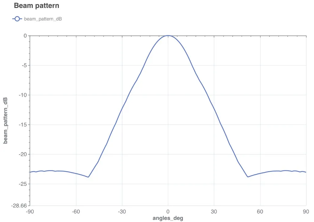
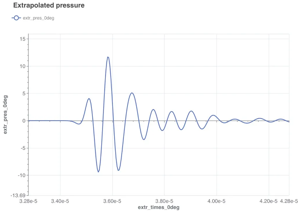
The Z Displacement Field visualization shows the propagating wavefield through the composite stack and into the water load.
Key performance indicators are available as scalar outputs:
| KPI | Output name |
|---|---|
| Centre frequency | FFT centre frequency (Hz) |
| Maximum Tx sensitivity | FFT maximum Tx sensitivity (Pa/V) |
| Impedance at centre | FFT impedance at centre (Ohm) |
| -6 dB fractional bandwidth | FFT fractional bandwidth |