
Meshing
Each project in Allsolve can contain multiple meshes, but simulations are only run on one mesh at a time.
To choose the mesh for your simulation, select next to Mesh:
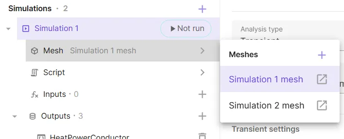
Meshes depend on the geometry and are generated based on the given mesh settings. After a mesh has been successfully generated, it can be used in all simulations.
The mesh list displays all meshes in a tree structure. Each mesh contains its basic settings (mesh element size, mesh quality), customizations (refinements, transfinite entities, extrusions) and mesh instances (default instance and any variable override instances).
Autorefine
Section titled “Autorefine”The Autorefine toggle determines whether the meshing algorithm automatically deduces element sizes or strictly follows user-defined mesh size settings.
-
Enabled (Default): The meshing algorithm attempts to automatically deduce suitable sizing that follows the given settings but also ensures mesh quality. For example, if maximum size setting applies to some entity, the sizing for nearby entities is determined suitably to avoid ill-shaped mesh elements. If meshing fails due to low quality elements, the mesher will retry by refining the sizing in places where these elements appeared.
-
Disabled: The mesher follows the given size restrictions accurately and typically works well if it is ensured that the size settings are suitable for all geometrical entities. However, it cannot deduce suitable sizing automatically.
Mesh size settings
Section titled “Mesh size settings”Mesh size presets
Section titled “Mesh size presets”Mesh size is controlled through a preset setting that provides three predefined presets: Coarse, Default, and Fine.
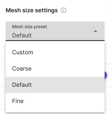
Selecting a preset automatically populates the mesh element size fields with appropriate values:
- Coarse
- Minimum size: 0.1% of the geometry size
- Maximum size: 20% of the geometry size
- Curvature enhancement:
- Target maximum width-to-height ratio:
- Default
- Minimum size: 0.01% of the geometry size
- Maximum size: 10% of the geometry size
- Curvature enhancement:
- Target maximum width-to-height ratio:
- Fine
- Minimum size: 0.001% of the geometry size
- Maximum size: 5% of the geometry size
- Curvature enhancement:
- Target maximum width-to-height ratio:
Changing any predefined element size value while using presets Coarse, Default, and Fine automatically switches the preset to Custom.
Mesh element size
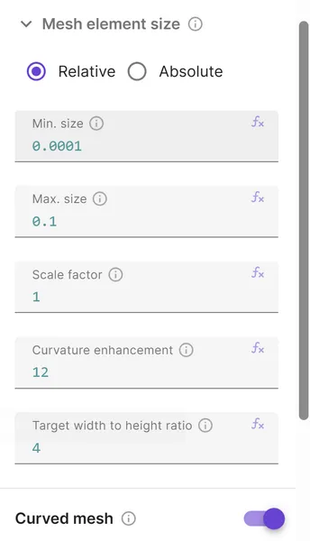
Section titled “Mesh element size”Size settings restrict the mesh size globally. Local adjustments can be made through customizations. Maximum size, curvature enhancement, and target width-to-height ratio set an upper bound for the mesh size. The effect of these can be limited by setting minimum size. The resulting sizing can be fine-tuned with scale factor.
Size mode
Section titled “Size mode”Element sizes can be specified in two modes:
- Relative (default): Sizes are expressed as a fraction of the total geometry size. Values are between and . For example, a value of represents 10% of the geometry size. The geometry size is obtained from the model’s bounding box - the distance between (, , ) and (, , ) of the bounding box.
- Absolute: Sizes are specified directly in meters.
Maximum and minimum size
Section titled “Maximum and minimum size”Maximum size sets the maximum size for mesh elements. This requirement is always fulfilled.
Minimum size sets the minimum size, but note that this cannot be strictly enforced. For example, each curve entity should have at least one mesh element, and the minimum size setting cannot be followed if the given minimum size is greater than the curve length. This setting should be seen as a way to limit the effect of the other settings that set an upper bound for the mesh size.
When using relative size mode, these values represent fractions of the geometry size. When using absolute size mode, values are in meters.
Curvature enhancement
Section titled “Curvature enhancement”Curvature enhancement limits the mesh size based on the curvature of the geometrical entities. This improves the accuracy with which the mesh follows curved geometries.
The given value determines the minimum number of elements that are used to represent a full circle (elements per 360 degrees). Use value to disable this feature.
Target width-to-height ratio
Section titled “Target width-to-height ratio”This setting sets a target maximum width-to-height ratio of elements. The feature measures distance to nearby entities and attempts to limit the mesh size in thin regions where the given target would otherwise be violated.
For example, consider two parallel surfaces whose distance from each other is , and suppose we are using the default value for target maximum width-to-height ratio. Then the mesh size should not exceed or the target maximum would be violated in the volume between them.
It should be noted that the setting is not fully exhaustive and is only used to limit the mesh size when it is clear that the requested maximum width-to-height ratio would otherwise be violated. There is no way to directly control the aspect ratios of individual mesh elements.
This feature is only available with autorefine enabled. Use value to disable the feature. Unless disabled, the value should be at least . Lower values typically improve the average element quality but increase the number of elements, so there is no single optimal value for all cases.
Scale factor
Section titled “Scale factor”Scale factor is a multiplier applied to the mesh sizing before the mesh is generated. The scaling is applied after all other sizing, with the exception that global and entitywise maximum sizes are always followed. It does not affect structured meshing.
This is especially useful if the mesh requires fine-tuning. For example, if you would like to decrease (or increase) the element size by 10%, try scale factor (or ). Lower values (for example, for 10% sized elements) typically also work, but note that values much greater than are not guaranteed to work. It is not always possible to coarsen the mesh, and the mesh quality may deteriorate especially in case of curved geometries.
Curved mesh
Section titled “Curved mesh”This option enables the use of curved, second-order elements for better accuracy on curved geometries. The first-order mesh is always generated first. If enabled, all elements are then converted to second-order elements that capture the geometry more accurately. Finally, mesh optimization is performed to ensure validity of the resulting mesh. This may sometimes fail but typically works well if the initial mesh is not too coarse.
Mesh element quality
Section titled “Mesh element quality”The mesh element quality setting controls how low-quality elements are handled during meshing. Three parameters are available:
- Fail tolerance: The maximum percentage of low-quality elements allowed. If the percentage exceeds this value, meshing fails.
- Optimization tolerance: The percentage of low-quality elements that is allowed before the optimization is retried. The mesher attempts to reduce the count of low-quality elements below this threshold.
- Max optimization iterations: The maximum number of optimization iterations the mesher performs trying to reach the optimization tolerance.
Runtime
Section titled “Runtime”Meshing runtime settings are configured per mesh and control the computational resources allocated to the meshing job:
- Node type: The type of compute node used for meshing.
- Duration: The maximum time the meshing job is allowed to run before it times out.
Customizations
Section titled “Customizations”Use customizations to make local adjustments to the mesh. Four types of customizations are available: mesh refinement, transfinite meshing, autotransfinite meshing, and mesh extrusion.
To use a customization, select next to Customizations and add the desired type.
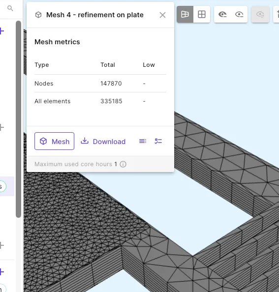
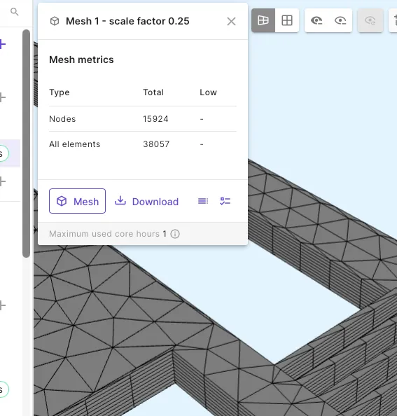
Mesh refinement
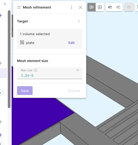
Section titled “Mesh refinement”Mesh refinement is similar to the maximum size setting but it is only applied to a specific region in the geometry. Mesh refinement can target volumes, surfaces or curves. Once the target type is selected, fill in the refinement value in meters. Any number of refinements can be added.
| Mesh refinement target | Meshing results (refinement on plate) | Meshing results (autorefine disabled) |
|---|---|---|
 |
 |
 |
Transfinite meshing
Section titled “Transfinite meshing”By default, all geometrical entities are meshed using unstructured meshing algorithms that handle arbitrarily complex geometries. When the geometry satisfies certain simplifying assumptions, transfinite and autotransfinite meshing can be used instead. It is also possible to combine structured and unstructured meshing so that selected entities are meshed using structured meshing and the rest are meshed unstructured afterwards.
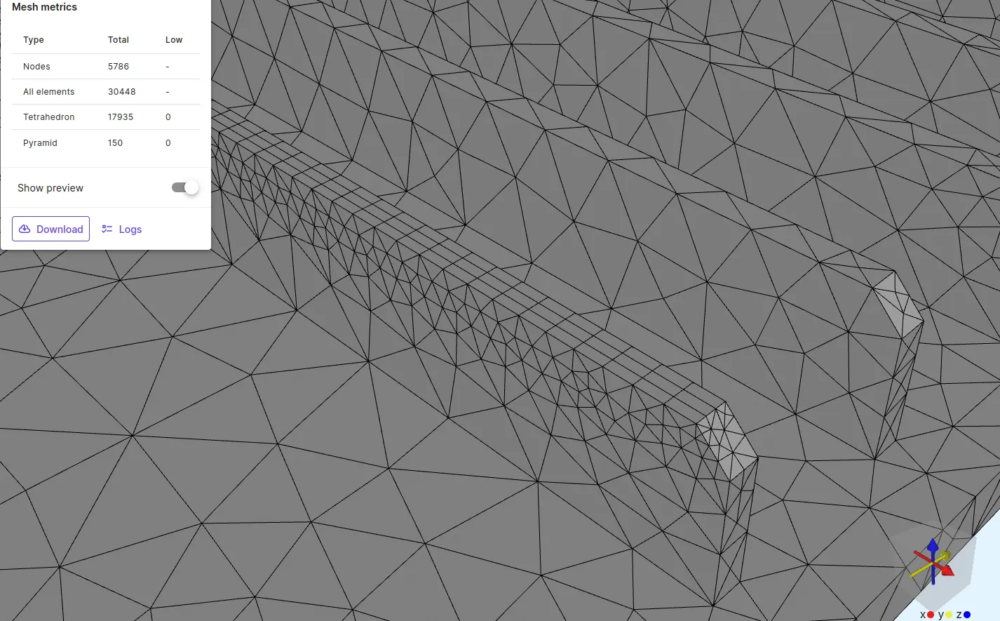
Structured meshing (transfinite and autotransfinite) is the only way to create nonsimplicial elements (for example quadrangles and hexahedra). When unstructured meshing is used to fill entities that have quadrangles on the boundary, pyramids are generated to combine these with tetrahedra.
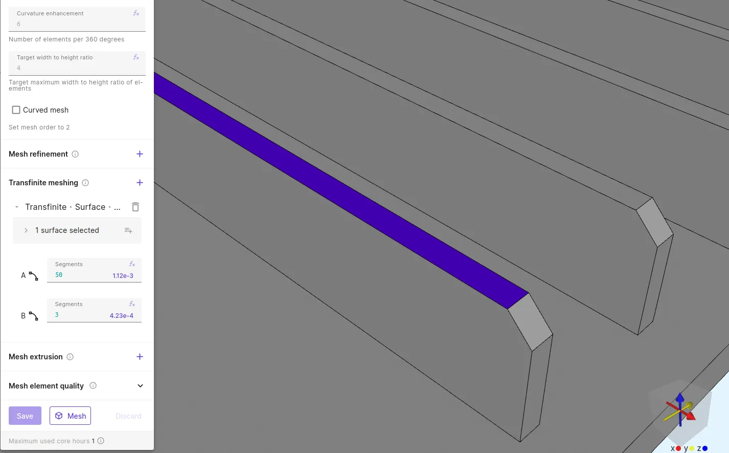
Transfinite meshing allows you to mesh curves, surfaces akin to a rectangle, or volumes akin to a box by specifying the number of elements to use on the curves in each direction. Surfaces and volumes are filled with quadrangles and hexahedra using transfinite interpolation.
- Choose the target entity (curve, surface, or volume) you want to set.
- Input values for each direction of curves in your selection (two curve segment counts for surface targets and three for volume targets). As you hover over a curve label (A/B/C), the corresponding curve in the model view will be highlighted.
- Allsolve calculates an average mesh element size based on your inputs. Aim to keep the ratios of the resulting lengths within a range of 1/3 to 3 for optimal results.
| Transfinite meshing target | Meshing result |
|---|---|
 |
 |
Autotransfinite meshing
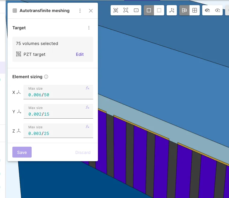
Section titled “Autotransfinite meshing”Autotransfinite meshing applies structured (transfinite) meshing to compatible geometrical entities without requiring you to specify element counts for each curve direction. Instead of segment counts, you provide target element sizes in meters along the axis-aligned directions. Allsolve automatically detects corners and sides, determines element counts for every curve, and ensures opposite sides of each surface have compatible counts. Surfaces are filled with a structured quad mesh and volumes with a structured hex mesh.
Compared to transfinite meshing, autotransfinite meshing is less tedious to set up and is geometry-independent: changing the geometry does not invalidate the configuration, sides may consist of multiple curves, and you can target surfaces and volumes directly.
- Select the target entities (volumes, surfaces, and/or curves) to mesh with structured elements.
- Input the target element sizes in the axis-aligned directions.
Multiple targets can reference the same entities with different sizes. When a curve is covered by more than one target, the finest (smallest) size wins per direction. This lets you layer coarse and fine sizing requirements over the same geometry. Element sizes are bounded by the global minimum and maximum size settings.
Limitations
Section titled “Limitations”Surfaces targeted for autotransfinite meshing:
- Must have no holes (inner wire loops).
- Must have no embedded entities (embedded points or curves).
- Must have at least 3 boundary curves.
- Must have connected boundary curves (consecutive curves must share an endpoint).
- Must have identifiable corners (at least 3 vertices with sufficiently sharp angles).
Volumes targeted for autotransfinite meshing:
- Must have exactly 6 boundary surfaces (hexahedral topology).
- Must have exactly 8 corners (each shared by 3 surfaces).
- Must have no voids (inner shells) or embedded entities.
Autotransfinite curves must not overlap with curves defined in transfinite meshing. If both define the same curve, meshing reports an error with the conflicting curve tags.
| Autotransfinite meshing target | Meshing result |
|---|---|
 |
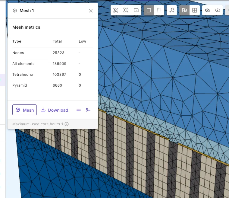 |
| In the piezoarray demo project, only the PZT rods are targeted for autotransfinite meshing. | A regular, hexahedral (cuboid) mesh on the rods, and an unstructured mesh elsewhere on the model. |
Mesh extrusion
Section titled “Mesh extrusion”Mesh extrusions create a 3D mesh by extruding a 2D surface mesh. Several extrusion types are available: simple extrusion, path extrusion, and slanted extrusion.
Mesh extrusions are especially useful if the geometry has thin layers where unstructured meshing is difficult. Meshing in 2D is typically much easier than in 3D, and extrusion preserves the element quality. It also enables different mesh sizing in horizontal and vertical direction.
The conformity of the resulting mesh is automatically ensured. For example, when extrusion is applied to stacked volumes, the surface mesh of the lower volume must already be generated in a way that allows the extrusion to continue to the entities in the upper volume. This can usually be achieved without any problems. However, issues may occur if the upper volume contains entities that are essentially the same as in the lower volume but slightly misplaced due to issues with the geometry. In this case extrusion might fail during the 2D meshing phase or it might result in thin mesh elements.
Simple extrusion
Section titled “Simple extrusion”Simple mesh extrusions use unstructured meshing to mesh bottom surfaces and extrude the elements of this surface mesh to obtain a 3D mesh. They can be applied to volumes whose curves and surfaces are either horizontal or vertical (perpendicular or parallel to the Z-axis).
The number of elements to use in the Z-direction will be specified by the user as follows. To make the mesh consistent with the geometry, extrusion should match with all different Z-levels that have horizontal entities. This prescribes a minimum number of layers.
The number of sublayers to use within each layer can be selected freely, and the user is required to input these sublayer counts.
To use this feature, add a Mesh extrusion -> Simple extrusion under Customizations, and configure the following options:
| Target | Select the volumes where extrusion is applied. |
| Sublayers | Select a sublayer count for each layer. |
| Overlap Mode | Whether to allow or prevent generation of pyramids on the sides of extruded volumes. Prevent mode will abort meshing with an error if any extruded volume is detected to share a vertical surface with a volume that is not extruded. This check is not included in Allow mode. |
Path extrusion
Section titled “Path extrusion”Path extrusions extrude a surface mesh along a specified path curve, allowing mesh generation for geometries that follow a non-linear path.
Slanted extrusion
Section titled “Slanted extrusion”Slanted extrusions extrude a surface mesh between specified “from” and “to” surfaces, supporting geometries where the extrusion direction is not aligned with the coordinate axes.
Mesh instances
Section titled “Mesh instances”Each mesh has one or more mesh instances. A mesh instance represents a single meshing run with a specific set of parameters.
Default instance
Section titled “Default instance”Every mesh has a Default mesh instance. This instance simply uses the mesh settings as configured, without any variable overrides. The default instance is always visible in the mesh tree under the mesh item.
Variable override instances
Section titled “Variable override instances”If geometric definitions and mesh settings use expressions with variable overrides, these can be attached to a mesh. Each attached variable override creates additional mesh instances. When meshing is started, the mesher generates separate mesh files for each value in the variable override. To add a variable override to the mesh, select next to Overrides on the mesh item.
Mesh instance panel
Section titled “Mesh instance panel”Contents of the mesh instance panel depends on the job status of the mesh generation:
| Not run | Running | Success |
|---|---|---|
 |
 |
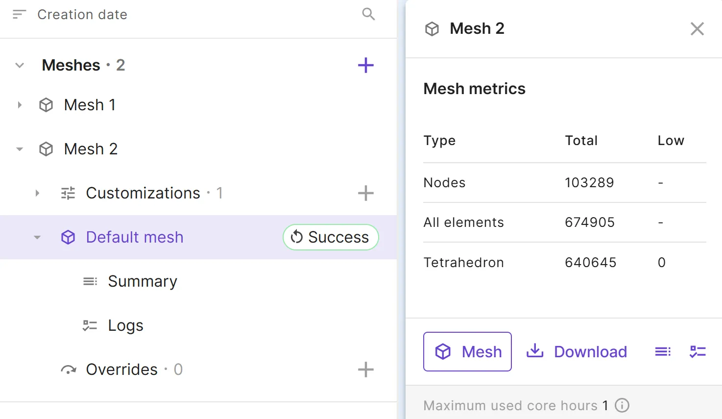 |
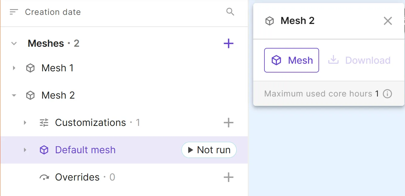
Mesh generation is started by selecting Mesh or by clicking the Not run button. |
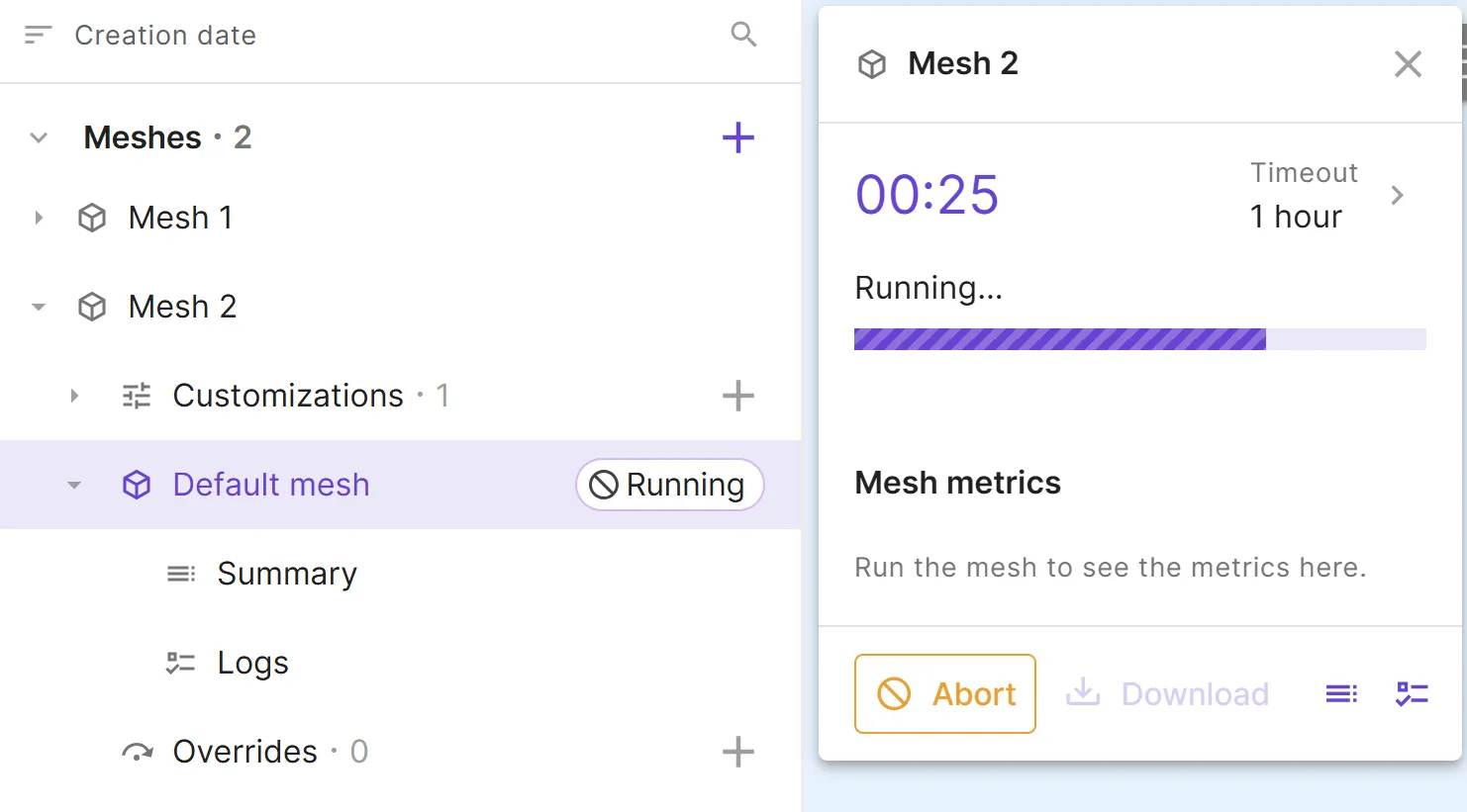
While meshing is in progress, the current job status and progress are shown. Meshing can also be aborted while in progress. | After the meshing is completed successfully, the panel displays Mesh metrics. |
Mesh metrics: total number of nodes, total number of elements, and element counts broken down by type. The count of low-quality elements is also displayed if any are present.
- Download: Download the generated mesh file (
.msh). For variable override instances with multiple mesh files, a ZIP archive is downloaded. - Summary: Open mesh summary.
- Logs: Open mesh logs.
Summary and Logs can also be accessed while the meshing job is running.
Mesh summary
Section titled “Mesh summary”The summary provides an overview of all meshing jobs of a mesh instance. It is accessible either from the mesh instance panel or from the mesh tree. For each mesh, the summary displays:
- Job status: Whether the job succeeded, failed, or is still running.
- Override values: For mesh instances with Overrides, the values of variable overrides used for each job.
- Download: A download button for each mesh file.
- Logs: A link to open logs for each individual job.
- Visualize: A button to preview the mesh in the model view.
Mesh logs
Section titled “Mesh logs”The mesh logs displays the output logs from meshing jobs. It is accessible either from the mesh instance panel, the summary or the mesh tree.
For mesh instances with Overrides, logs are organized in separate tabs. The main job tab is always shown; additional child job tabs can be added by selecting and choosing a child job from the menu.
The Autoscroll toggle keeps the latest log output in view while meshing is in progress.
Mesh preview
Section titled “Mesh preview”For any selected mesh instance, the mesh preview is automatically rendered in the model view, assuming the meshing jobs were successfully completed. The mesh preview is also accessible via the Visualize button in the mesh instance summary.
For a mesh instance with Overrides, the preview opens a toolbar to the top right for stepping through each mesh corresponding to the values in your Overrides. You can also Visualize the next sweep step from the summary.
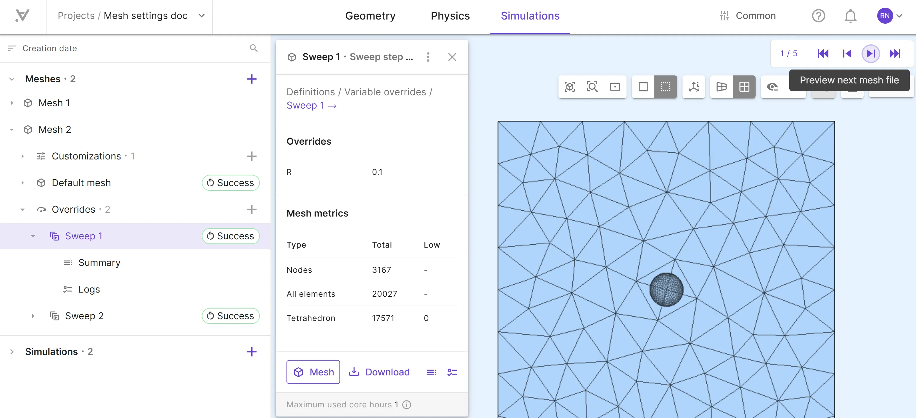
If a mesh instance with Overrides results in a partial success (some succeeded while others failed), the successfully generated mesh files can still be previewed individually.