
Piezoelectric material properties characterization
Piezoelectric material properties characterization predicts piezoelectric material properties from electrical impedance measurements of a disc-shaped piezoelectric sample.
The feature uses a pre-trained neural network to estimate elastic, piezoelectric, dielectric, and damping properties that can be used directly in piezoelectricity simulations in Quanscient Allsolve.
For general material setup — adding materials, configuring settings, and editing properties — see Working with materials.
Prerequisites
Section titled “Prerequisites”A circular, disc-shaped geometry is recommended, as the model is trained for circular disc samples measured under conditions that match the training data. Results for other geometries or measurement setups may be less accurate.
Opening the tool
Section titled “Opening the tool”- Open a project and go to the Physics section.
- Select next to Materials.
- From Generate material properties (beta), select Piezoelectric material.
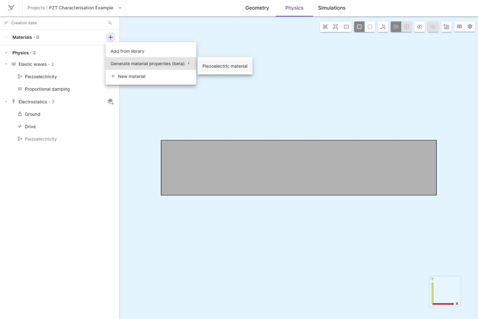
The workflow has three steps:
- Enter disc dimensions
- Upload and map impedance measurement data
- Review generated properties and add them as a new material
Step 1 — Disc parameters
Section titled “Step 1 — Disc parameters”Enter the physical dimensions of the measured disc:
| Parameter | Unit | Description |
|---|---|---|
| Diameter | mm | Diameter of the disc |
| Thickness | mm | Thickness of the disc |
| Weight | g | Mass of the disc |
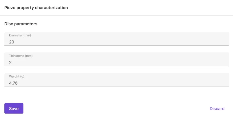
Density is computed automatically from weight and dimensions using a cylindrical volume model:
where is mass, is diameter, and is thickness.
Step 2 — Impedance measurement data
Section titled “Step 2 — Impedance measurement data”CSV file format
Section titled “CSV file format”Upload a comma- or tab-separated CSV file containing three columns:
| Column | Unit | Description |
|---|---|---|
| Frequency | Hz | Measurement frequency |
| Impedance magnitude | Magnitude of the electrical impedance | |
| Impedance phase | degrees | Phase of the electrical impedance |
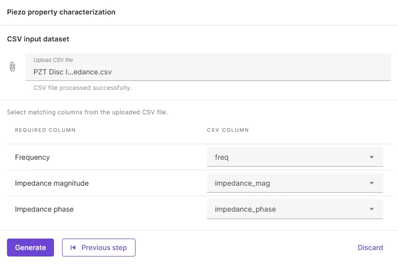
After uploading, map each required column to the corresponding column in your file. Column names are matched automatically when possible.
All three columns must contain the same number of data rows.
Validation rules
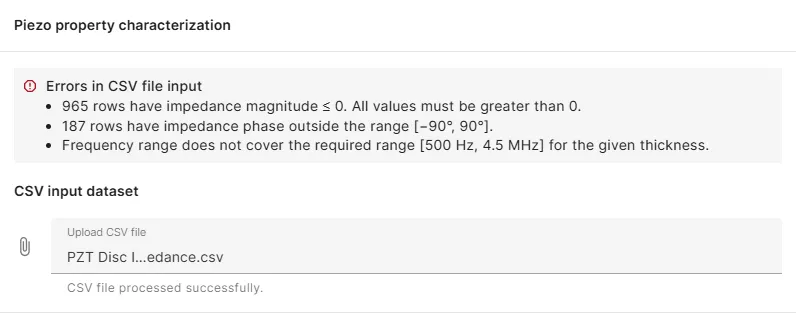
Section titled “Validation rules”The uploaded data is validated before generation:
| Check | Requirement |
|---|---|
| Impedance magnitude | All values must be greater than 0 |
| Impedance phase | All values must be in the range −90° to 90° |
| Frequency range | Must cover [1/t, 9000/t] Hz, where t is disc thickness in metres |
The required frequency range corresponds to a thickness-normalized grid of 1–9000 Hz·m, which is the range used by the underlying model. Wider coverage generally improves prediction quality.
Step 3 — Generated material properties
Section titled “Step 3 — Generated material properties”Click Generate to run the characterization. When complete, review the predicted material properties before adding them to your project.
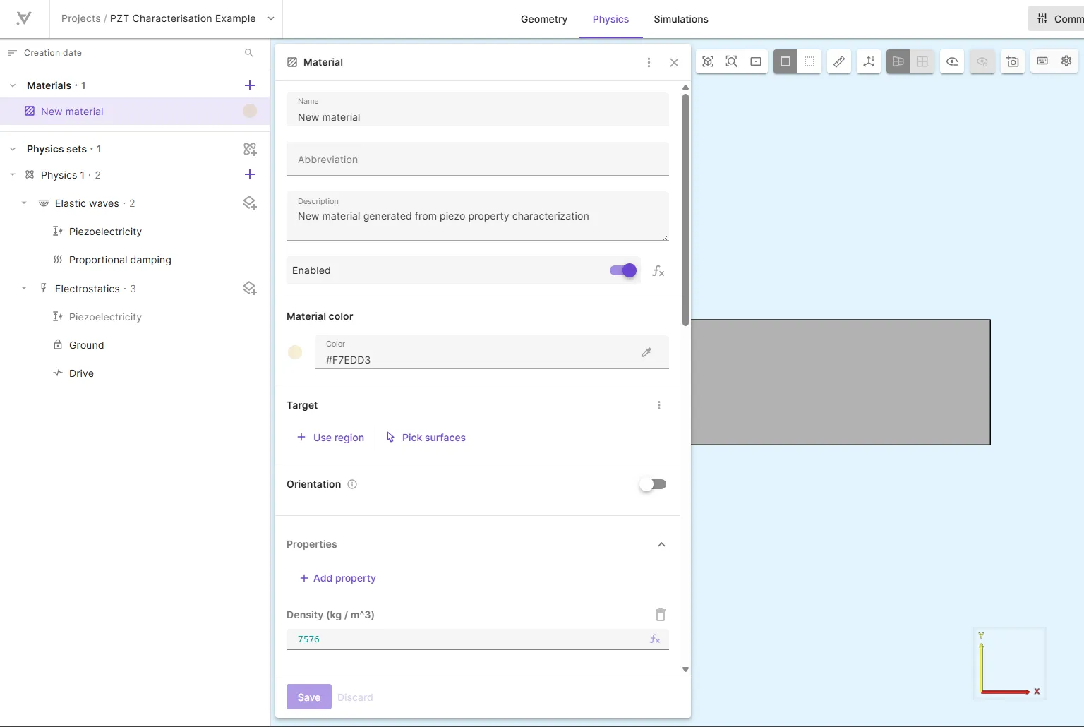
Click Add as new material to create a material with the generated properties. The new material is added to your project and can be assigned to regions like any other material.
Predicted properties
Section titled “Predicted properties”The model predicts the following material constants from your impedance data and disc geometry:
| Property | Symbol | Unit | Material property in Allsolve |
|---|---|---|---|
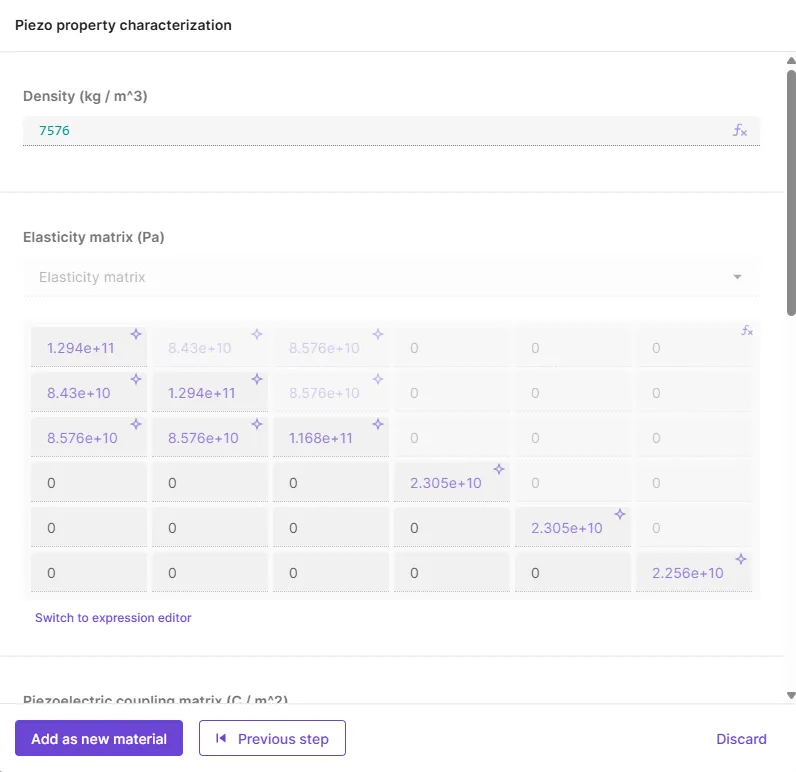
| Elastic stiffness | , , , , | Pa | Elasticity matrix |
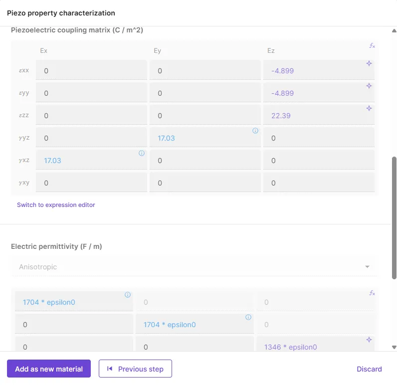
| Piezoelectric stress | , | C/m² | Piezoelectric coupling matrix |
| Relative permittivity | — | Electric permittivity (33 component) | |
| Mechanical quality factor | — | Mass and stiffness damping coefficients |
Density from the disc measurements is set as the Density property.
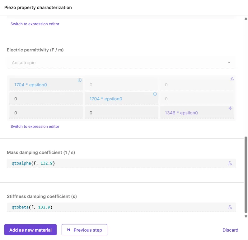
Damping coefficients are expressed using the mechanical quality factor through the qtoalpha(f, Q) and qtobeta(f, Q) functions, which convert into mass and stiffness proportional damping suitable for Solid mechanics and Elastic waves simulations.
See examples of predicted properties in the table below (click to enlarge image). The icon indicates predicted values. The icon marks values fixed from a reference PZT dataset.
| Density and Elasticity matrix | Piezoelectric coupling matrix and Electric permittivity | Damping coefficients |
|---|---|---|
 |
 |
 |
Generated vs fixed values
Section titled “Generated vs fixed values”In the preview, predicted values are marked with . Some matrix entries cannot be determined from a disc impedance measurement alone; these are taken from a reference PZT dataset and marked with :
| Material property | Fixed entries | Reason |
|---|---|---|
| Piezoelectric stress | Not identifiable from disc impedance alone | |
| Relative permittivity | , | Not identifiable from disc impedance alone |
The elasticity matrix also includes a derived shear component , computed from the predicted and values.
Adding the material to your project
Section titled “Adding the material to your project”After reviewing the generated properties, select Add as new material. The material is created with all predicted and fixed properties, and appears in your project’s Materials list ready to be assigned to regions.
Limitations
Section titled “Limitations”- Sample geometry: The model is designed for disc-shaped samples. Other shapes are not supported.
- Fixed matrix entries: Properties that cannot be extracted from disc measurements use reference PZT values and may not match your specific material in those components.
- Prediction accuracy: Results depend on measurement quality, frequency coverage, and how closely your sample matches the training conditions. Treat outputs as estimates and validate against known data or experiments when possible.
- Third party processing: The feature requires third party services to be enabled for your organization.
Troubleshooting
Section titled “Troubleshooting”| Issue | Possible cause |
|---|---|
| Frequency range error | Measurement data does not span the required range for the given disc thickness |
| Impedance magnitude error | One or more magnitude values are zero or negative |
| Impedance phase error | One or more phase values fall outside −90° to 90° |
| Generation failed | Invalid or incomplete input data; check CSV mapping and disc parameters |
If generation fails after validation passes, verify that all disc parameters are positive numbers and that the CSV contains numeric values in every mapped column.