
MEMS 000 - Importing .gds files & mesh extrusion
Prerequisites: complete any one step-by-step tutorial first so you are comfortable with the Allsolve project layout (Geometry, Physics, Simulations, Results).
In MEMS simulations, models can get quite complicated and it is often best to start with an existing CAD-file for a model geometry.
In this documentation, some MEMS example cases start out with importing a .gds file, which is covered in detail in the GDSII Import guide.
Another important technique for MEMS simulations is creating the mesh through Mesh extrusion. In this example, that is also covered in more detail.
Importing a .gds file
Section titled “Importing a .gds file”See the GDSII Import guide for detailed steps on uploading a .gds file, configuring layer stacks, and building a 3D model.
Mesh extrusion
Section titled “Mesh extrusion”A mesh extrusion can be performed in the Quanscient Allsolve Simulations section as follows:
- Click
+next to Meshes to create a new mesh. - Set Autorefine to
Disabled. - Under
Customizations, add Mesh extrusion. - Select the mesh extrusion Target. To target all volumes, click
Select all.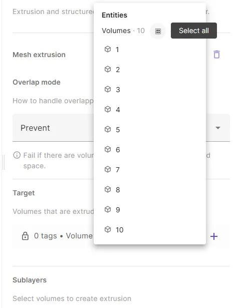
- Now, the mesh extrusion tool should recognize all separate extrusion layers in the target. Select a sublayer count for each layer.
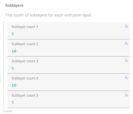
- Click
Apply & mesh. Characteristically for an extruded mesh, your mesh elements should form sublayers parallel to each other, like in the image below.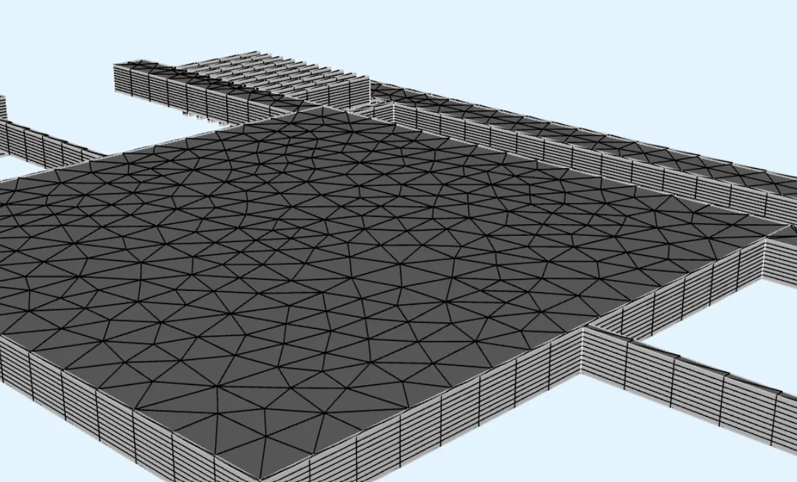
- If the sublayers in a layer are too thick or too thin, edit the sublayer count for that layer accordingly, and remesh.
- If the mesh is otherwise too dense or too sparse, try another Scale factor value and remesh.
Now, your mesh extrusion is complete.