
MEMS 002 - Combdrive static deflection
Prerequisites: complete MEMS 001 — Combdrive eigenmodes first — this example extends that model with an air box and electrostatic actuation.
In this example case, static deflection is simulated in a MEMS comb-drive accelerometer.
Model definition
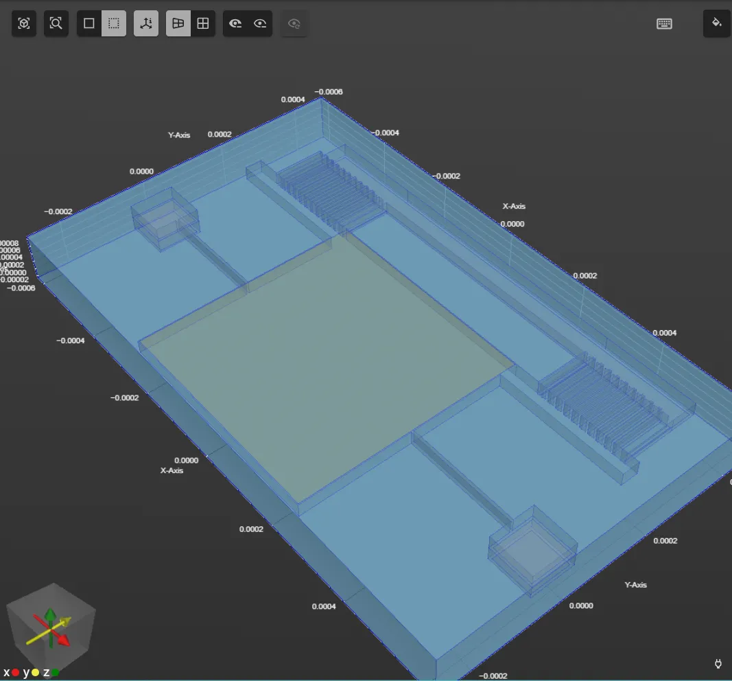
Section titled “Model definition”The same model is used for the comb-drive as in MEMS 001 - Combdrive EigenModes. Here, an air box is added around the comb-drive:
Simulation setup guide
Section titled “Simulation setup guide”Step 1 - Build the geometry
Section titled “Step 1 - Build the geometry”-
Import the comb-drive model exactly as in MEMS 001 - Combdrive EigenModes.
-
After the comb-drive model is imported, build the air box around it:
Name Element type Center point Size Rotation box Box X: 0X: 1250e-6X: 0Y: 100e-6Y: 750e-6Y: 0Z: 30.65e-6Z: 111.5e-6Z: 0
Step 2 - Define variables and materials
Section titled “Step 2 - Define variables and materials”-
Go to the
Commonsidebar. -
Define a variable:
Name Description Expression voltage voltage applied to the fixed comb 20 -
Proceed to the
Physicssection. -
Assign the
Airmaterial to the air box. -
Assign
Goldto the square top plate. -
Assign
Silicon dioxideto the thin silicon dioxide layers: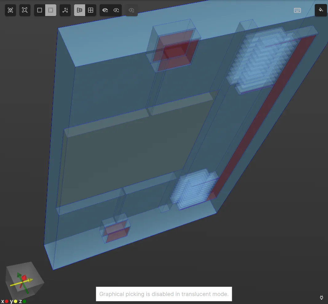
-
Assign
Monocrystalline siliconto the thick monocrystalline silicon layers: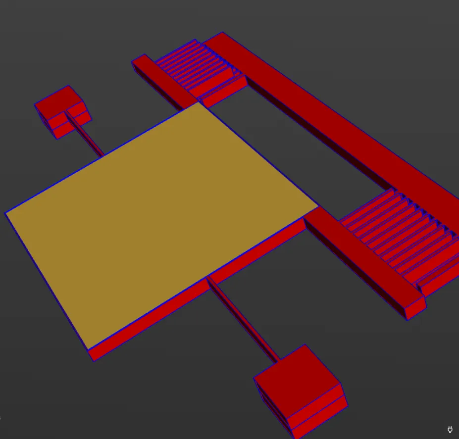
Step 3 - Define the physics
Section titled “Step 3 - Define the physics”Proceed to the Physics section to define the physics.
For static deflection, the Solid mechanics, Electrostatics and Mesh deformation physics are required.
Physics 1 - Solid mechanics
Section titled “Physics 1 - Solid mechanics”- As solid mechanics target, select all volumes except the air box.
- Add the target as a region with name
Solid domain.
- Add the target as a region with name
- Add
Clamp.- As target, select the bottom silicon dioxide layers.
- Add
Large displacement. - Add
Electric force.
Physics 2 - Electrostatics
Section titled “Physics 2 - Electrostatics”- Leave the electrostatics target as empty, letting it default to all volumes.
- Add
Constraint, and name it as Voltage.- As target, select the fixed comb volumes.
- Set constraint value to
voltage.
- Add
Constraint, and name it as Ground.- As target, select the movable comb and top plate volumes.
- Set constraint value to
0.
- Add
Large displacement.
Physics 3 - Mesh deformation
Section titled “Physics 3 - Mesh deformation”- As mesh deformation target, select the region
Electric domain. - Add
Constraint.- As target, select the region
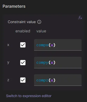
Solid domain. - As value, use expressions as in the image below.
- As target, select the region
Your simulation physics are now defined.
Step 4 - Generate the mesh
Section titled “Step 4 - Generate the mesh”Proceed to the Simulations section to generate the mesh:
- Create a new mesh.
- Set Autorefine to
Disabled. - Under
Customizations, add Mesh extrusion with all volumes as target. - Set the sublayer counts as necessary.
- Click
Apply & mesh.
Step 5 - Simulate
Section titled “Step 5 - Simulate”In the Simulations section, create a new simulation:
- Analysis type
Static
- Solver mode
Iterative solver
- Relative residual tolerance
1e-6
- Mesh
- Select the mesh you created in Step 4.
- Input
- Add
voltage sweepwith override expressionlinspace(0, 1, 10).
- Add
- Output
- Add
ufield output. - Add
vfield output. - Add
Efield output.
- Add
Run the simulation.
Step 6 - Visualize
Section titled “Step 6 - Visualize”In the Simulations section, add visualizations to see field output results.
To see u field results, for example:
- Add a visualization.
- On the visualization, add
u (real). - On u, add
Warp. - Set warp scale factor to
1e-3.