MUTs 001 - PMUT array
Prerequisites: complete any one step-by-step tutorial first so you are comfortable with the Allsolve project layout (Geometry, Physics, Simulations, Results).
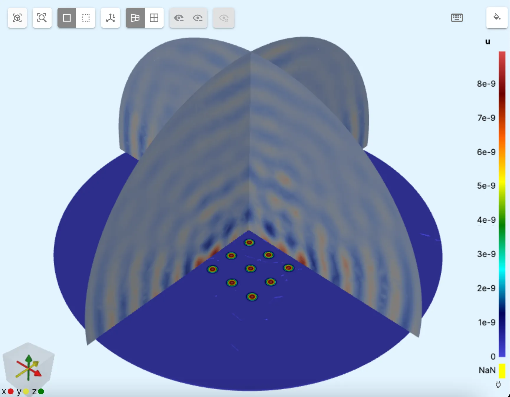
In this example, ultrasound emitted by a 6x6 array of PMUTs (Piezoelectric micromachined ultrasonic transducers) is modeled and simulated.
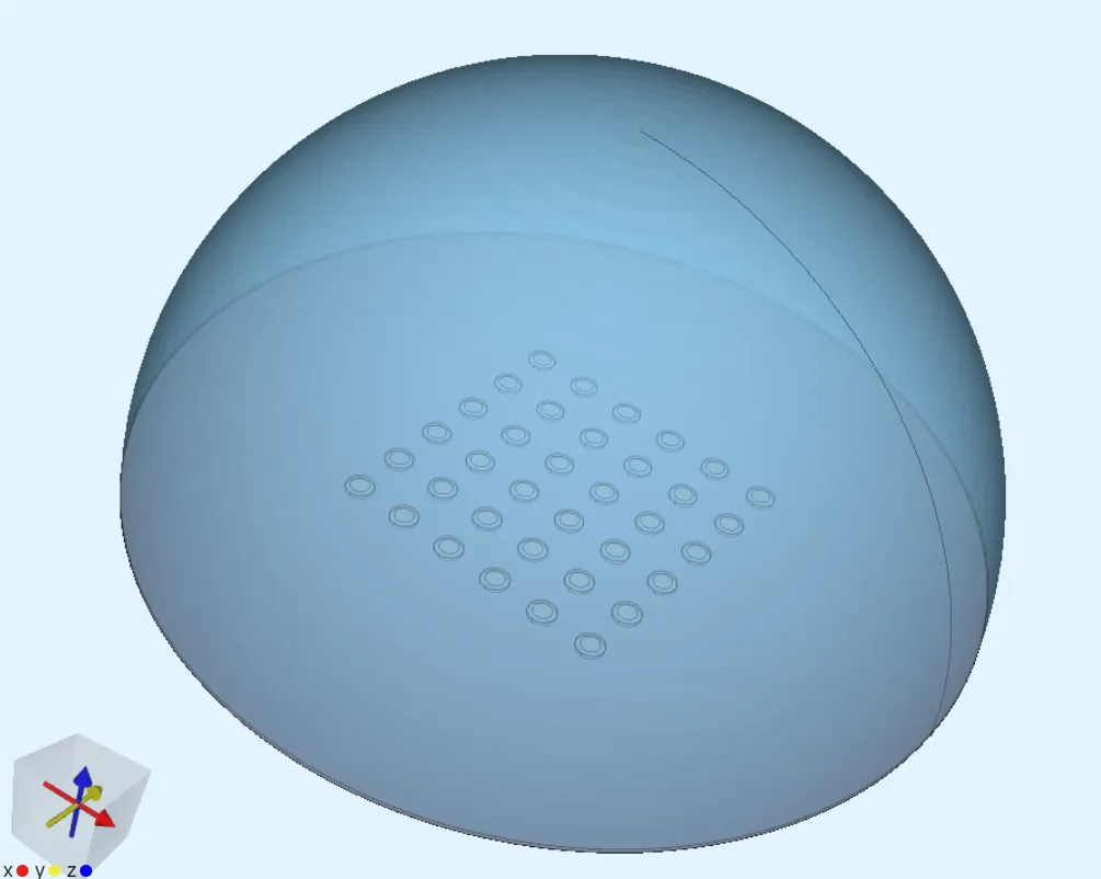
This example corresponds to the demo project 6x6 PMUT array
Simulation setup guide
Section titled “Simulation setup guide”Here you’ll find an example case level guide on modeling and setting up physics for a simple PMUT array in Quanscient Allsolve. See the last two steps for typical simulation options and visualizing results for harmonic ultrasound.
Variables
Section titled “Variables”Allsolve supports inline variable creation, so variables can be created on the fly during modeling. Optionally, you can define all the variables first, and then move on to modeling.
Here is a list of all the variables used in this tutorial:
| Name | Expression | Description |
|---|---|---|
| R | 100e-6 |
Cavity radius |
| thmem | 10e-6 |
Membrane thickness |
| thpiezo | 2e-6 |
Piezo thickness |
| thcavity | 20e-6 |
Cavity thickness |
| n | 6 |
Array size (even numbers only) |
| Rair | 5*R*n |
Air bubble radius |
| freq | 1e6 |
Frequency |
Step 1 - Modeling
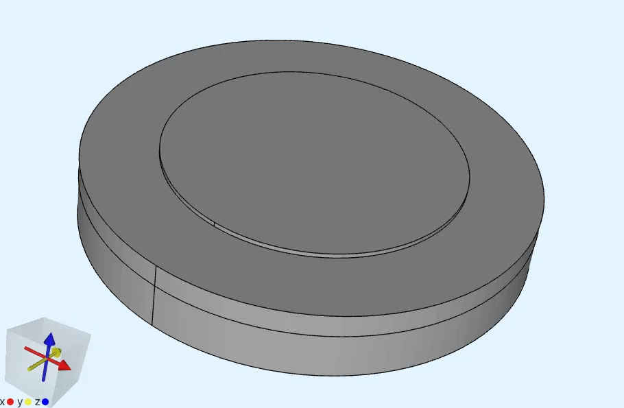
Section titled “Step 1 - Modeling”- Build one of the PMUTs by creating 3 cylinders in a stack:
| Name | Element type | Center point (m) | Size (m) | Rotation (deg) |
|---|---|---|---|---|
| Membrane | Cylinder | x: 0 |
Radius: R |
x: 90 |
y: 0 |
Height: thmem |
y: 0 |
||
z: 0 |
z: 0 |
| Name | Element type | Center point (m) | Size (m) | Rotation (deg) |
|---|---|---|---|---|
| Piezo | Cylinder | x: 0 |
Radius: 0.67 * R |
x: 90 |
y: 0 |
Height: thpiezo |
y: 0 |
||
z: thmem/2+thpiezo/2 |
z: 0 |
| Name | Element type | Center point (m) | Size (m) | Rotation (deg) |
|---|---|---|---|---|
| Cavity | Cylinder | x: 0 |
Radius: R |
x: 90 |
y: 0 |
Height: thcavity |
y: 0 |
||
z: -thcavity/2-thmem/2 |
z: 0 |
- Use the Grid operation to make the 6x6 array of PMUTs:
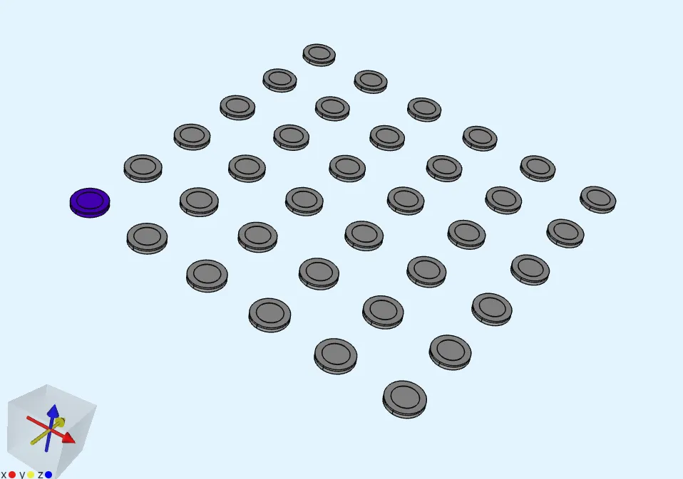
| Name | Element type | Target volumes | Translation | Repeat count |
|---|---|---|---|---|
| Grid | Grid operation | all 3 cylinder volumes of the single PMUT | x: 4*R |
x: n |
y: 4*R |
y: n |
|||
z: 0 |
z: 0 |
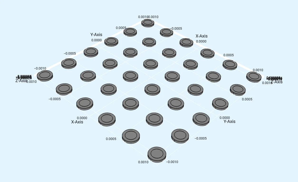
- Select all volumes in the grid and translate them so that your array is centered at the origin
[0,0,0]:
| Name | Element type | Target volumes | Translation |
|---|---|---|---|
| Translate | Translate operation | All volumes in the grid | x: -4*R*(n-1)/2 |
y: -4*R*(n-1)/2 |
|||
z: 0 |
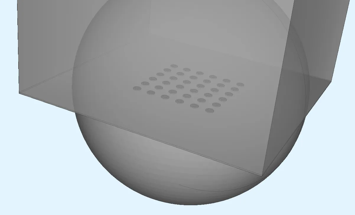
- Build a sphere and 2 mostly overlapping boxes for the air bubble and baseplate:
| Name | Element type | Center point (m) | Size (m) |
|---|---|---|---|
| Sphere | Sphere | x: 0 |
Radius: Rair |
y: 0 |
|||
z: 0 |
| Name | Element type | Center point (m) | Size (m) | Rotation (deg) |
|---|---|---|---|---|
| Box | Box | x: 0 |
x: 2*Rair |
x: 90 |
y: 0 |
x: 2*Rair |
y: 0 |
||
z: Rair+thmem/2 |
x: 2*Rair |
z: 0 |
| Name | Element type | Center point (m) | Size (m) | Rotation (deg) |
|---|---|---|---|---|
| Box 2 | Box | x: 0 |
x: 2*Rair |
x: 90 |
y: 0 |
x: 2*Rair |
y: 0 |
||
z: Rair-thmem/2-thcavity |
x: 2*Rair |
z: 0 |
-
Apply the Fragment all operation.
-
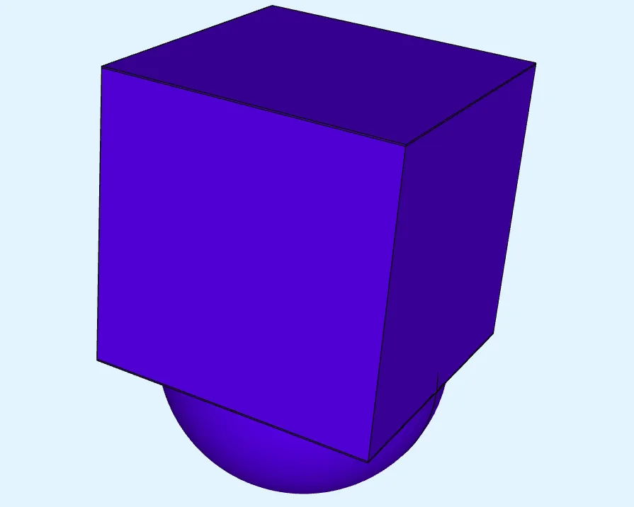
Remove extra box and sphere sections (4 volumes in total, selected as in picture below).
-
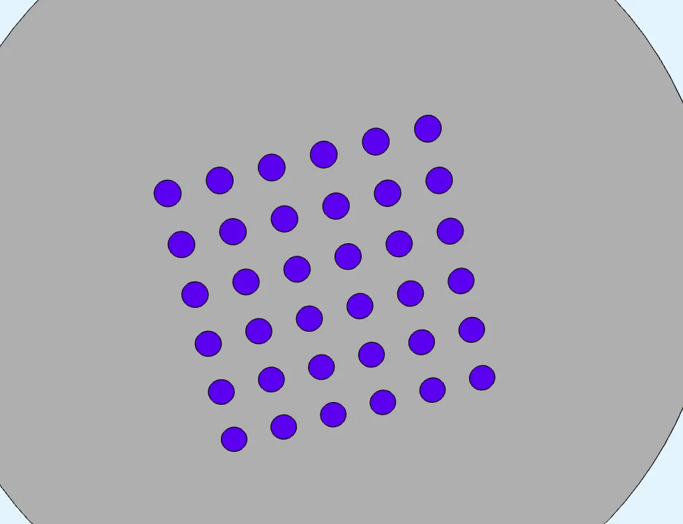
Remove the cavity disc volume under each PMUT in the array.
Step 2 - Materials
Section titled “Step 2 - Materials”Proceed to the Physics section to define the model materials.
- Assign
Airfrom the material library to the air bubble volume. Save the target as a region. - Create a Geometry selector type region called
pzt. Include the small top disc of each PMUT in the region. This is easiest to do by setting both Minimum size and Maximum size with one of the small discs. Use the Pick similar tool to select the disc for min and max size.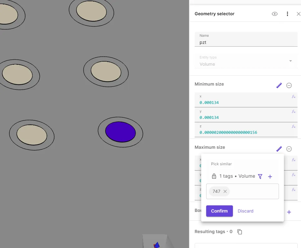
- Assign
PZTfrom the material library to thepztregion.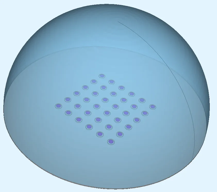
- Create a region called
all, containing all volumes. It is easiest to do this by creating a computed region and picking the Complement of nothing. This way theallregion is also updated if your geometry changes. - Create a Computed region type region.
Call it
mono-si, and include all the remaining volumes, i.e. the membrane disc of each PMUT as well as the large circular baseplate. To pick these volumes easily, use the Difference operation. Select regionsall,pztandAir targetfor the operation. The difference of these regions yields the volumes highlighted below (air bubble hidden):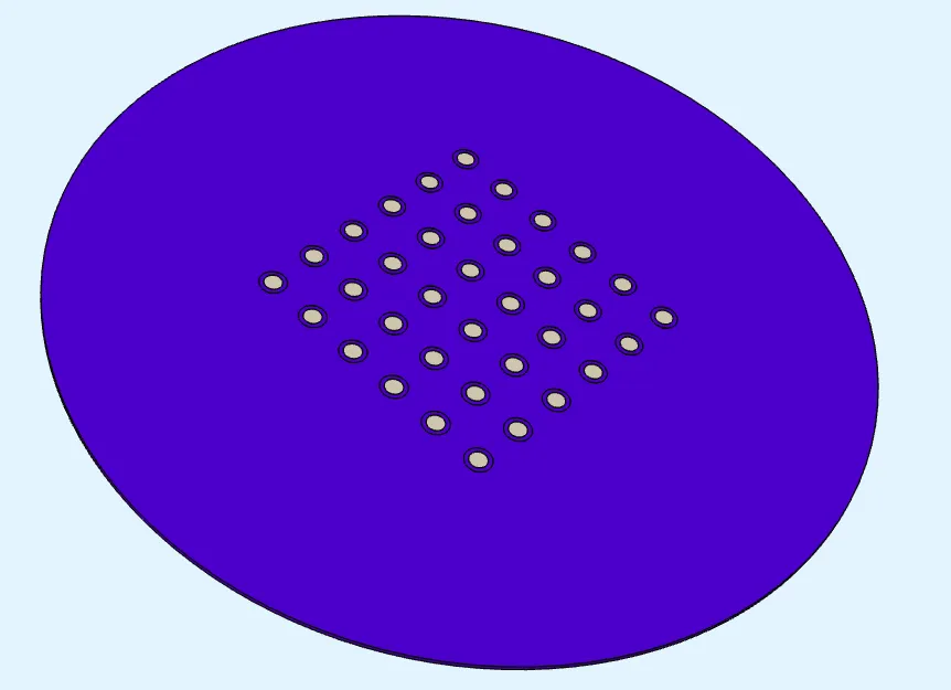
- Assign
Monocrystalline siliconfrom the material library to themono-siregion.
Step 3 - Physics
Section titled “Step 3 - Physics”In total, 3 physics are used in this example: Elastic waves, Acoustic waves and Electrostatics.
Add all of them to your project, after which you can move on to defining their interactions.
Physics 1 - Elastic waves
Section titled “Physics 1 - Elastic waves”- As elastic waves target, select all volumes except the air bubble.
- Add a
Clampinteraction.- As clamp target, select the baseplate volume.
- Add the Elastic waves–Electrostatics coupling
Piezoelectricity.- As piezoelectricity target, select the
pztregion.
- As piezoelectricity target, select the
Physics 2 - Acoustic waves
Section titled “Physics 2 - Acoustic waves”- As acoustic waves target, select the air bubble.
- Add
Perfectly matched layer.- As perfectly matched layer target, select the air bubble dome surface.
- Set PML Type to
AML.- AML is suitable for rounded surfaces such as an air bubble, whereas box PML is built for XYZ-aligned box surfaces.
- Add the Acoustic waves–Elastic waves coupling
Acoustic structure.
Physics 3 - Electrostatics
Section titled “Physics 3 - Electrostatics”- As electrostatics target, select the
pztregion. - Add a
Constraintinteraction.- As constraint target, select the bottom surface of each PZT disc on the array, 36 in total.
To avoid clicking a large number of surfaces manually, you can define a geometry selector region with a bounding box for the surfaces.
To avoid picking the larger PMUT membrane surfaces that exist on the same plane, use Pick similar for max size.
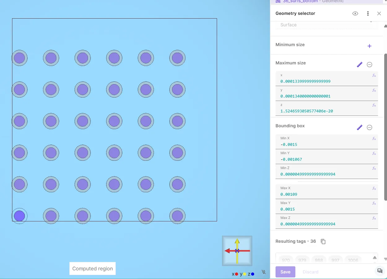
To pick surfaces on a certain Z-plane with geometry selector, it’s recommended to use the exact same value for Z Min and Z Max. Surface localization in a very thin Z-slice can be inaccurate due to floating point errors. If Z min and max are set as the same value however, a buffer is set to both directions to pick planar surfaces reliably.
- Set constraint value to
0.
- As constraint target, select the bottom surface of each PZT disc on the array, 36 in total.
To avoid clicking a large number of surfaces manually, you can define a geometry selector region with a bounding box for the surfaces.
To avoid picking the larger PMUT membrane surfaces that exist on the same plane, use Pick similar for max size.
- Add a
Lump V/Qinteraction.- As lump V/Q target, select the top surface of each PZT disc on the PMUTs.
Again, define a geometry selector region with a bounding box to save some clicks.
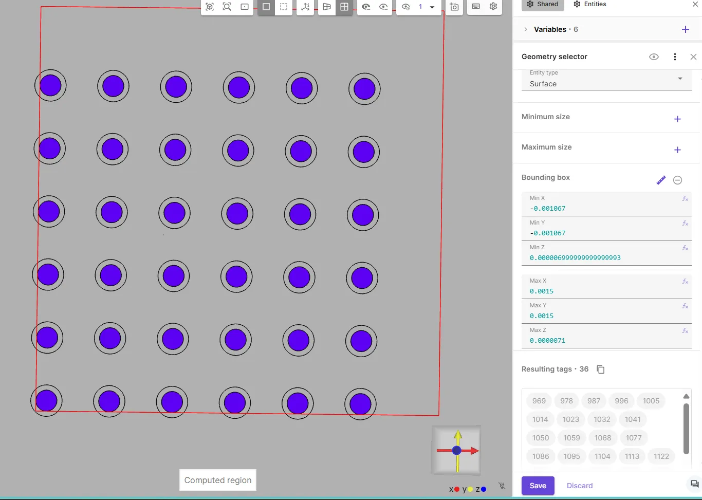
- Set Actuation mode to
Voltage. - Set voltage to
sin(2*pi*freq*t).
- As lump V/Q target, select the top surface of each PZT disc on the PMUTs.
Again, define a geometry selector region with a bounding box to save some clicks.
Step 4 - Meshing
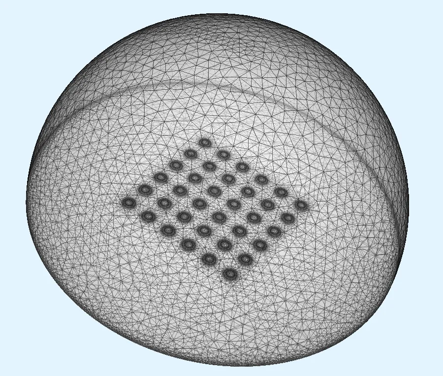
Section titled “Step 4 - Meshing”- Add a mesh.
- Open the collapsible menu for
Mesh element size. - Set Max size to
1e-4. - Save settings & mesh.
Step 5 - Simulation options
Section titled “Step 5 - Simulation options”Create a simulation with following options:
- Set Analysis type to
Harmonic. - Set Fundamental frequency to
freq. - Set Number of FFT samples to
3. - Set Node count to
10. - As the Mesh, select the mesh you created.
- For Inputs, create a sweep:
- Create a Sweep override over variable
freq. - Set Override expression to
linspace(0.7e6, 0.9e6, 41). - Add the sweep to simulation inputs.
- Create a Sweep override over variable
- In Outputs, add:
u harmonic 2field- Skin only
p harmonic 2field- Skin only
- See demo project for custom value output examples.
Step 6 - Results
Section titled “Step 6 - Results”In the Simulations section, add visualizations and plots as needed.
The u field can be visualized in the air bubble using a slice filter for example: