Permanent Magnets
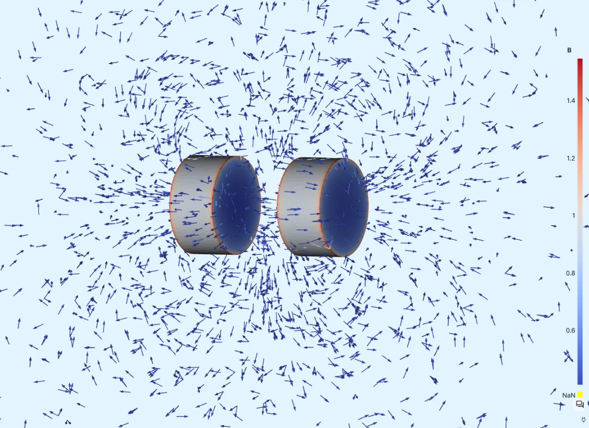
In this tutorial, the magnetic fields and magnetic forces resulting from a pair of small permanent magnets is simulated.
Model definition
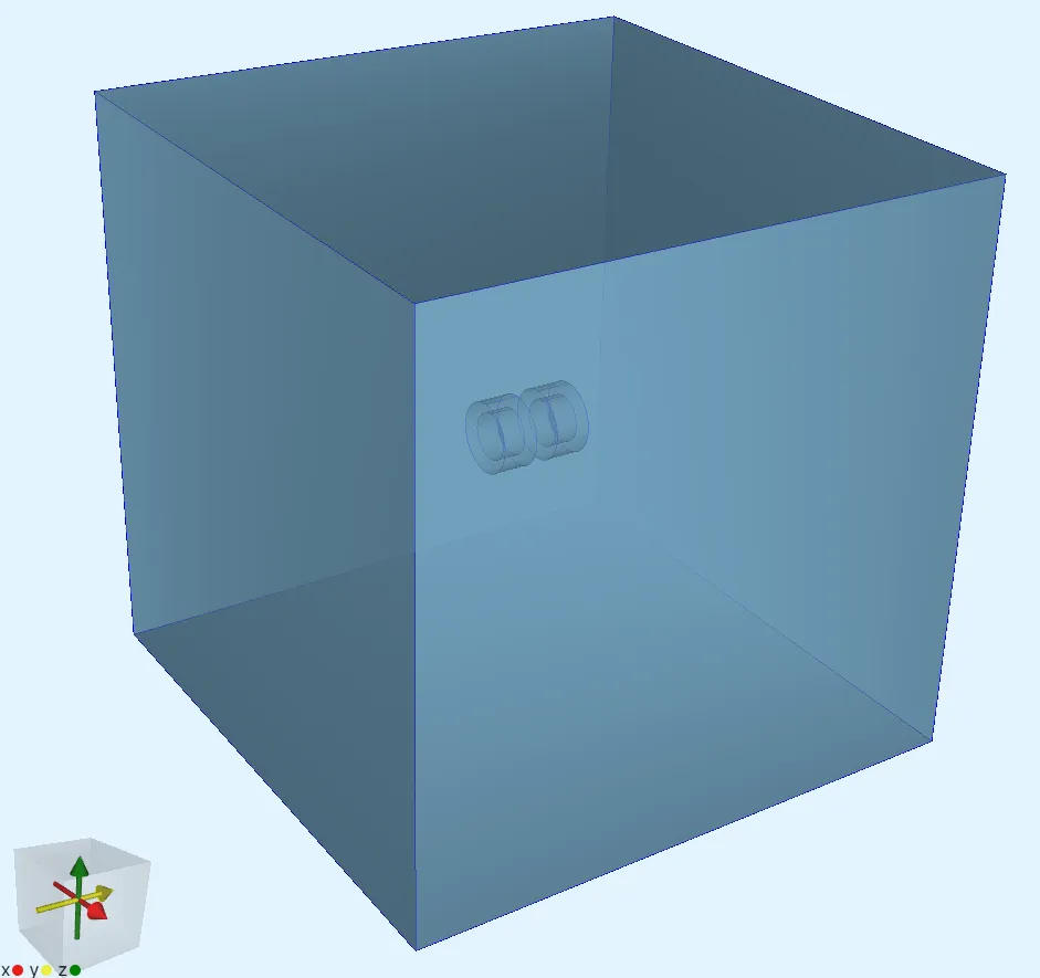
Section titled “Model definition”The model consists of two cylindrical 2 mm permanent magnets separated by a distance of 1.2 mm and an air box surrounding them.
A constant magnetic flux density is applied to the magnets. The resulting magnetic forces are determined with the Magnetism-φ formulation.
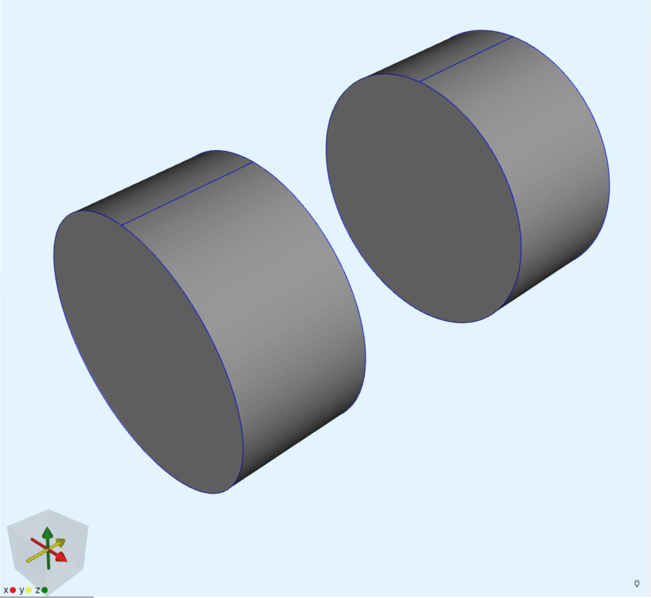
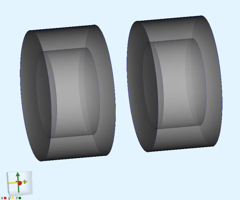
Additional cylindrical force domain volumes are created around the magnets, so that the magnetic fields around the magnets can be integrated.
| Element | Geometric details |
|---|---|
| Magnet 1 | Cylinder of 2 mm radius and 2 mm height centered at |
| Magnet 2 | Cylinder of 2 mm radius and 2 mm height centered at |
| Force domain 1 | Cylinder of 3 mm radius and 3 mm height centered at |
| Force domain 2 | Cylinder of 3 mm radius and 3 mm height centered at |
| Air box | Box of size 50 mm 50 mm 50 mm |
Output Results
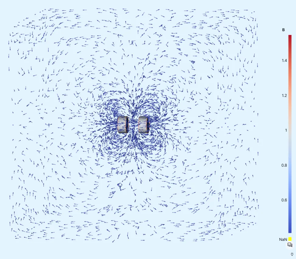
Section titled “Output Results”- Magnetic field distribution.
- Magnetic forces between the magnets.
Material Data
Section titled “Material Data”- Air
| Property | Value |
|---|---|
| Magnetic permeability |
Boundary conditions
Section titled “Boundary conditions”| Type | Value | Target volume |
|---|---|---|
| Remanence | [0, 1.35, 0] | Magnet 1 |
| Remanence | [0,-1.35, 0] | Magnet 2 |
Step-by-step guide
Section titled “Step-by-step guide”Here you’ll find a detailed step-by-step tutorial on how to simulate a pair of permanent magnets and the resulting forces in Quanscient Allsolve.
Step 1 - Build the geometry
Section titled “Step 1 - Build the geometry”-
Create a new project and name it
Permanent magnets. -
Start off with a
cylinderelement.Name Element type Center point [m] Size [m] Rotation [deg] magnet 1 Cylinder X: 0Radius: 2e-3X: 90Y: 2.5e-3Height: 2e-3Y: 0Z: 0Z: 0 -
Reset view after building
magnet 1to bring the small magnet cylinder back into view. -
Copy
magnet 1to buildmagnet 2.Name Element type Center point [m] Size [m] Rotation [deg] magnet 2 Cylinder X: 0Radius: 2e-3X: 90Y: -2.5e-3Height: 2e-3Y: 0Z: 0Z: 0 -
Copy
magnet 1to buildforce domain 1.Name Element type Center point [m] Size [m] Rotation [deg] force domain 1 Cylinder X: 0Radius: 3e-3X: 90Y: 2.5e-3Height: 3e-3Y: 0Z: 0Z: 0 -
Copy
force domain 1to buildforce domain 2.Name Element type Center point [m] Size [m] Rotation [deg] force domain 2 Cylinder X: 0Radius: 3e-3X: 90Y: -2.5e-3Height: 3e-3Y: 0Z: 0Z: 0At this point, there are 4 cylinders in the model, so that the force domains envelop the magnets that are facing each other.
-
Build the air box.
Name Element type Center point [m] Size [m] Rotation [deg] box Box X: 0X: 50e-3X: 0Y: 0Y: 50e-3Y: 0Z: 0Z: 50e-3Z: 0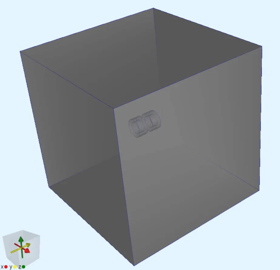
Step 2 - Define materials
Section titled “Step 2 - Define materials”-
Go to the
Physicssection. -
Assign the
Airmaterial to all volumes.Air is assigned to all volumes because in magnetostatics the relevant material property is the magnetic permeability (), which is the same for air and the magnets. The magnets are distinguished by their remanence boundary condition applied in the next step.
Step 3 - Define the physics and apply boundary conditions
Section titled “Step 3 - Define the physics and apply boundary conditions”-
Add the
Magnetism ϕinteraction. Let the target default to all volumes.Physics Target Magnetism φ All volumes -
Add a
Remanenceinteraction to Magnetism φ. Remanence introduces a B-field to a volume.Interaction name Interaction type Target Value Remanence left Remanencemagnet 2 [0; 1.35; 0]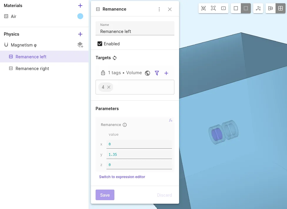
-
Add another
Remanenceinteraction to Magnetism φ.Interaction name Interaction type Target Value Remanence right Remanencemagnet 1 [0; -1.35; 0]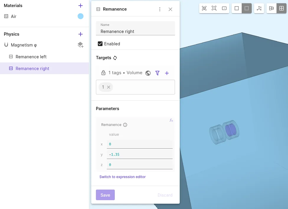
Step 4 - Generate the mesh
Section titled “Step 4 - Generate the mesh”-
Go to the
Simulationssection. -
Create a new mesh.
-
Open the collapsible menu for
Mesh element size. -
Set Max size to
0.05. -
Under
Customizations, add aMesh refinemententity of typeVolume. -
Select all cylindrical volumes to target and set its Max size to
0.0001.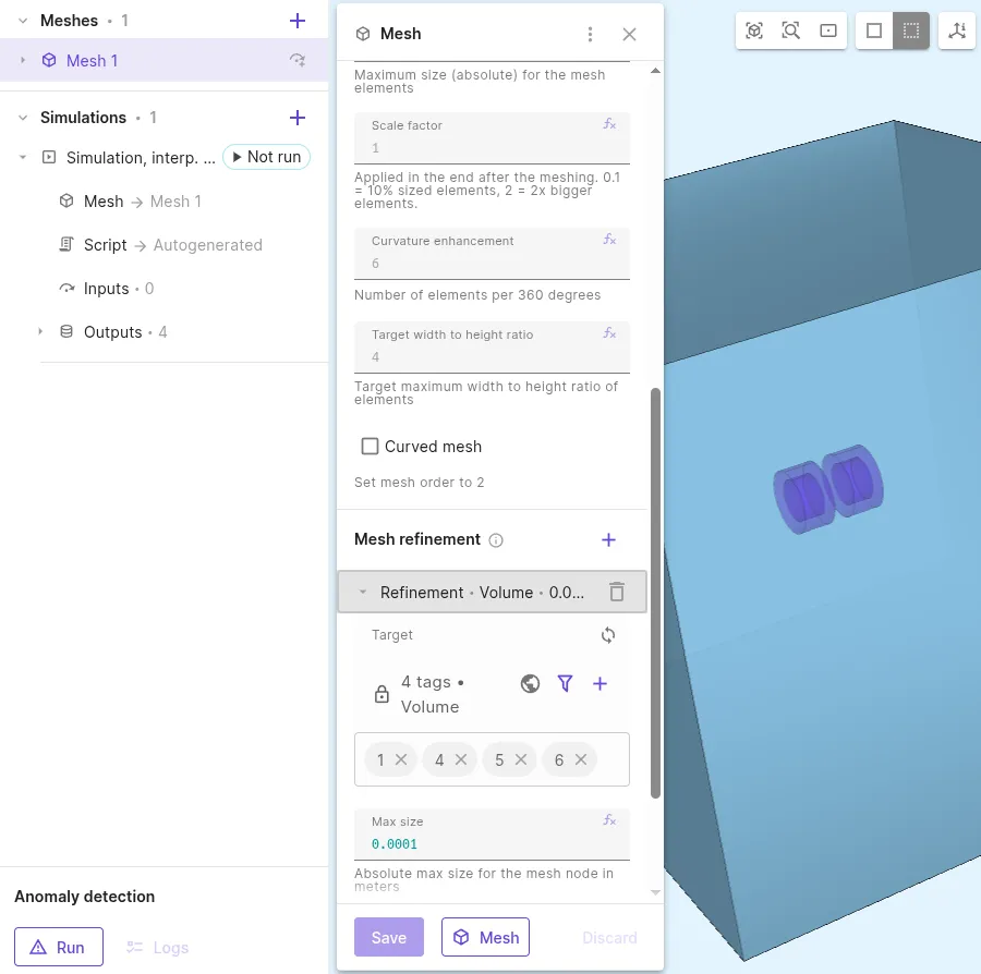
-
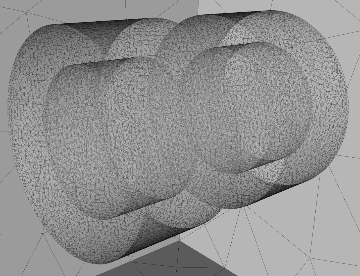
Generate the mesh and check the preview.
Step 5 - Apply simulation settings
Section titled “Step 5 - Apply simulation settings”-
Create a new simulation.
Simulation name Analysis type Node count Node type Simulation 1 Static 51 CPU, 16 GB -
Select
Mesh 1as the mesh for your simulation. -
Add a
Bfield output.Output name Output type Target Output expression B magnets Magnetic flux density ( B) field outputmagnets 1 and 2 B -
Add another
Bfield output.Output name Output type Target Output expression B air Magnetic flux density ( B) field outputForce domains 1 and 2, air box B -
Add a
Magnetic forcevalue output.Output name Output type Target Magnetic force left Magnetic force value output magnet 2 and force domain 2 -
Add another
Magnetic forcevalue output.Output name Output type Target Magnetic force right Magnetic force value output magnet 1 and force domain 1 -
Run the simulation.
Step 6 - See results
Section titled “Step 6 - See results”-
Check
Summaryfor the magnetic force value outputs.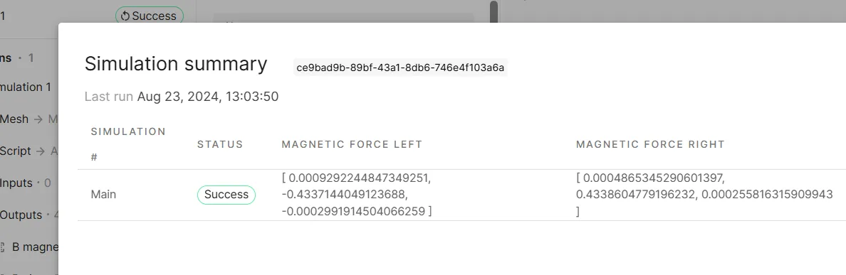
-
Add a visualization to see field output results:
Visualization name Fields Filters Visualization 1 B magnets B air Glyph -
Edit the
Glyphsettings:Filter Max sample points Scale factor Glyph 500000.001 -
Render the visualization.
-
The
Glyphscale factor is reduced to0.0005here for a closer look: