
Bending of a cantilever beam
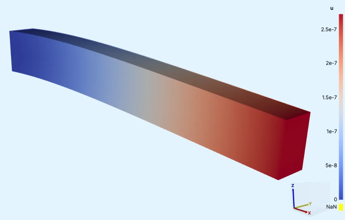
In this tutorial, the bending of a cantilever beam is simulated.
A cantilever is a rigid structure that extends horizontally and is unsupported at one end 1. It is widely used in construction and serves as a baseline simulation for structural mechanics.
Model definition
Section titled “Model definition”The model comprises a small aluminium beam built from a single box element. The beam is clamped from one of its end surfaces, and extends horizontally like a flagpole attached to a wall.
A load is evenly applied to the top surface of the beam, bending it downwards. The maximum Z-displacement is solved during simulation.
Model geometry
Section titled “Model geometry”| Name | Element type | XYZ dimensions [mm] |
|---|---|---|
| Cantilever beam | Box | 24 x 2 x 3 |
Material Data
Section titled “Material Data”Aluminium
Section titled “Aluminium”| Property | Value |
|---|---|
| Poisson’s ratio | 0.32 |
| Young’s modulus [Pa] | 68e9 |
Boundary conditions
Section titled “Boundary conditions”| Name | Target | Type | Value [X, Y, Z] |
|---|---|---|---|
| clamp | left X-plane | Clamp | [0, 0, 0] |
| load | top Z-plane | Load [N] | [0, 0, -1000] |
Output Results
Section titled “Output Results”Maximum Z-displacement.
Step-by-step guide
Section titled “Step-by-step guide”Below, you’ll find a detailed step-by-step tutorial on how to set up a cantilever beam simulation in Quanscient Allsolve.
Step 1 - Build the geometry
Section titled “Step 1 - Build the geometry”-
Start with a new project and name it
Cantilever beam. -
Start out with a
boxelement. A1 x 1 x 1m box is built by default. -
Edit the size of the box in settings:
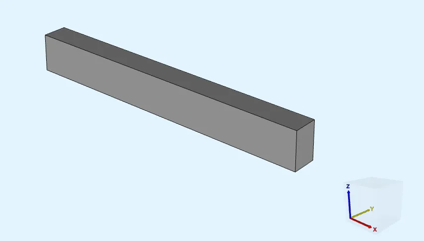
Name Element type Center point [m] Size [m] Rotation [deg] box Box X: 0X: 24e-3X: 0Y: 0Y: 2e-3Y: 0Z: 0Z: 3e-3Z: 0 -
Rebuild the box with correct dimensions.
-
Confirm model changes before moving on.
Step 2 - Define regions
Section titled “Step 2 - Define regions”-
Go to the
Commonsidebar. -
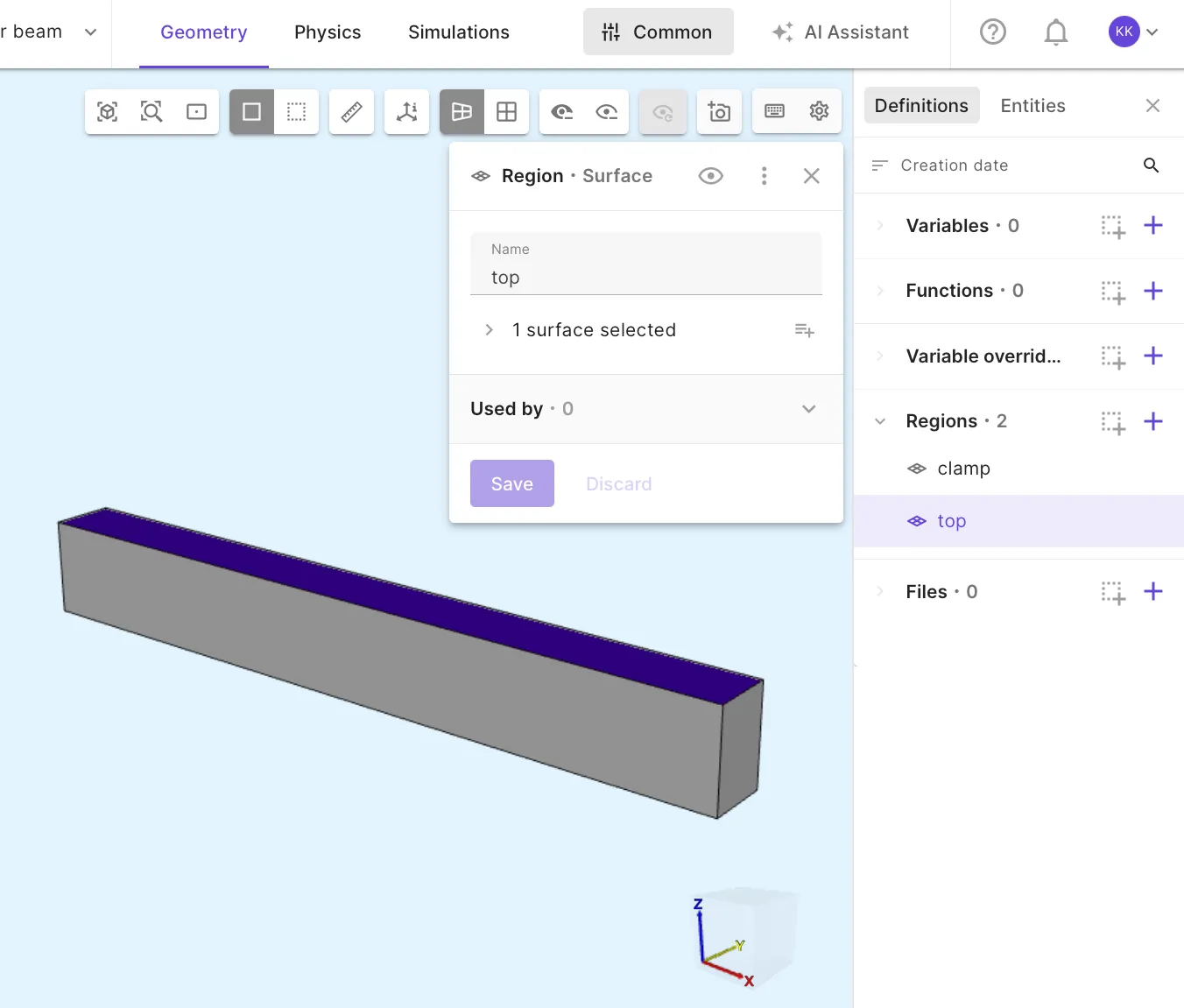
Define regions:
Name Region type Target clampSurface X direction bottom surface topSurface Z direction top surface.
Step 3 - Define the material
Section titled “Step 3 - Define the material”-
Go to the
Physicssection. -
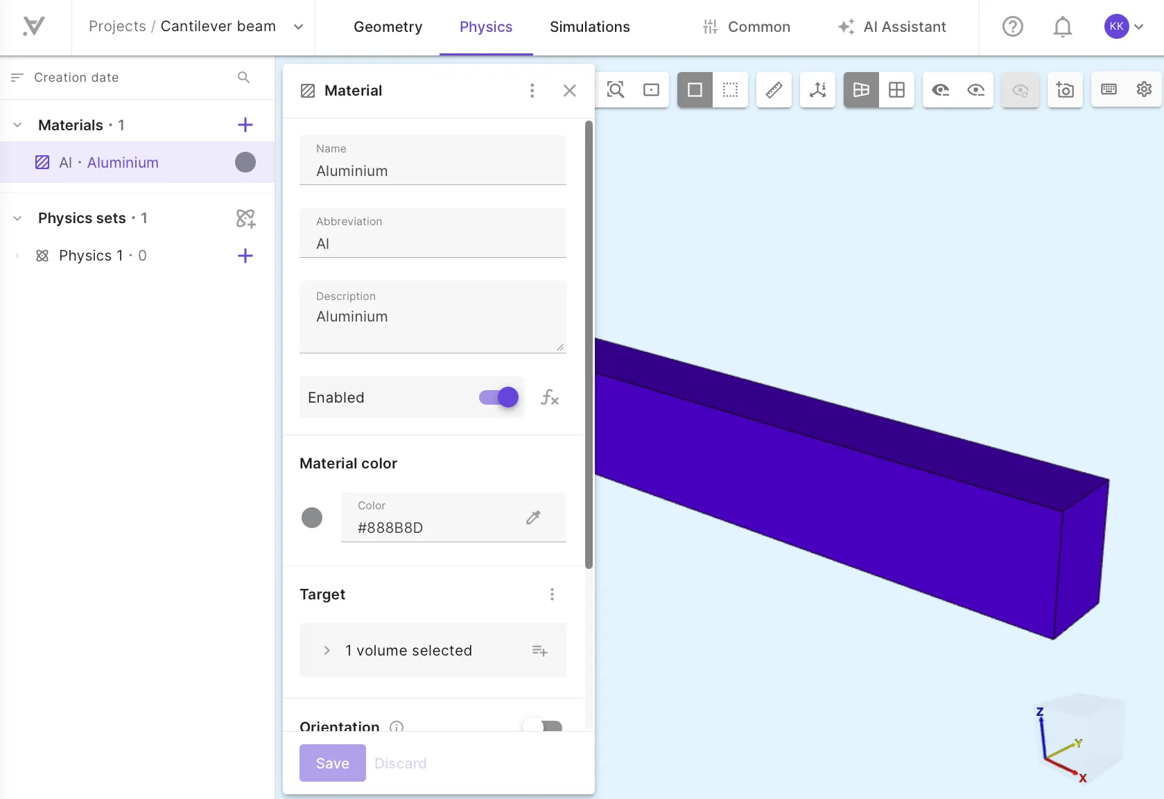
Add the predefined
Aluminiummaterial from the library. Assign it to the beam volume.
Step 4 - Define physics & boundary conditions
Section titled “Step 4 - Define physics & boundary conditions”-
Add the
Solid mechanicsphysics to Physics set 1.There is no need to select a target for solid mechanics, as it will default to the whole geometry.
Physics Target Solid mechanics Beam volume (default) -
Add a
Clampinteraction to Solid mechanics.This boundary condition constrains all components of the displacement vector in the target region to zero displacement: , , .
Name Interaction type Target Clamp Clampclampregion -
Add a
Loadinteraction to Solid mechanics.Name Interaction type Target Value [X; Y; Z] Load Loadtopregion[0; 0; -1000]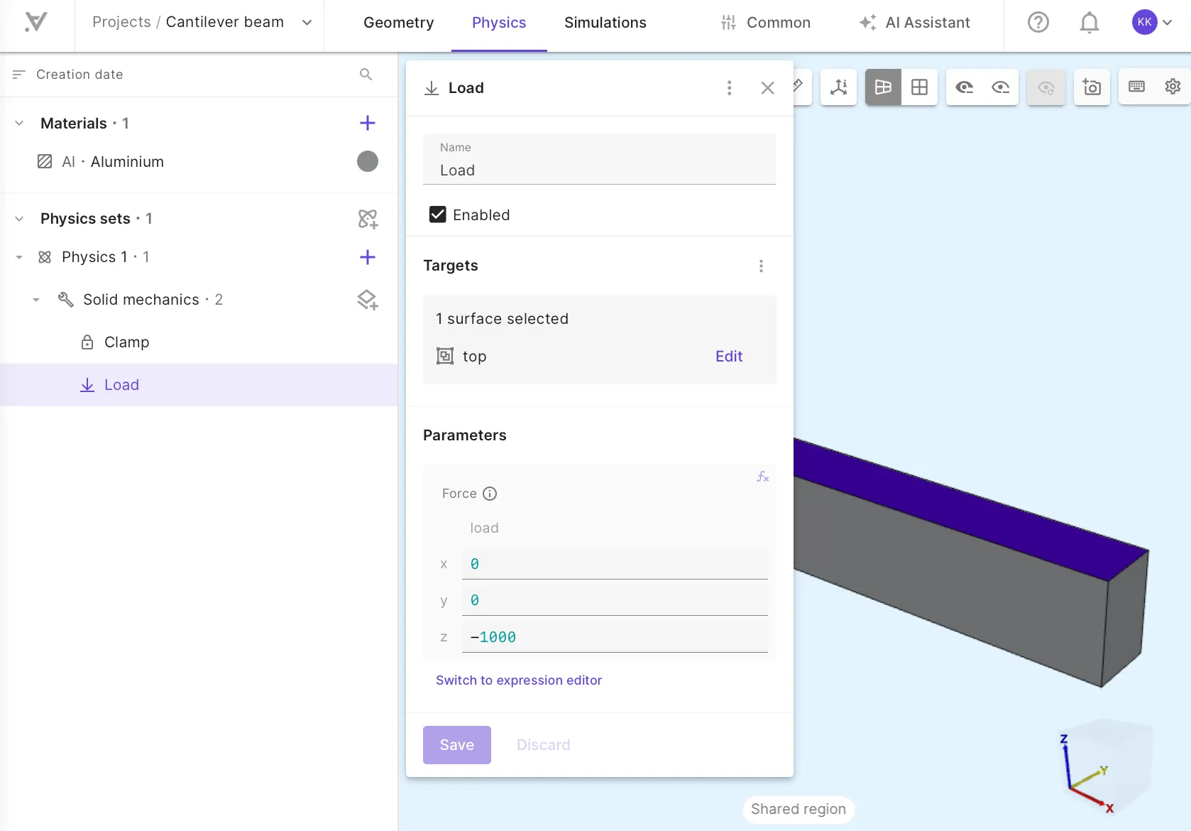
Step 5 - Generate the mesh
Section titled “Step 5 - Generate the mesh”-
Go to the
Simulationssection. -
Generate a new mesh with default settings.
-
Select Default mesh to open a preview of the mesh in the model view.
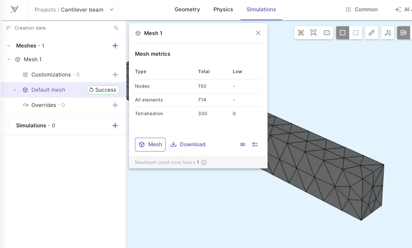
Step 6 - Apply simulation settings & run
Section titled “Step 6 - Apply simulation settings & run”-
Create a new simulation.
-
Set Analysis Type to
Static. -
Select the mesh you generated as the mesh for your simulation.
-
Add the displacement field output
u. -
Run the simulation.
Step 7 - Visualize results
Section titled “Step 7 - Visualize results”-
Add a visualization for the
ufield. -
Add
Warpto the visualization and activate it. -
Click Refresh next to Warp scale factor. Refreshing sets scale factor automatically to a reasonable number, in order to see the warping clearly.
-
Render the deformed geometry scaled up according to scale factor.
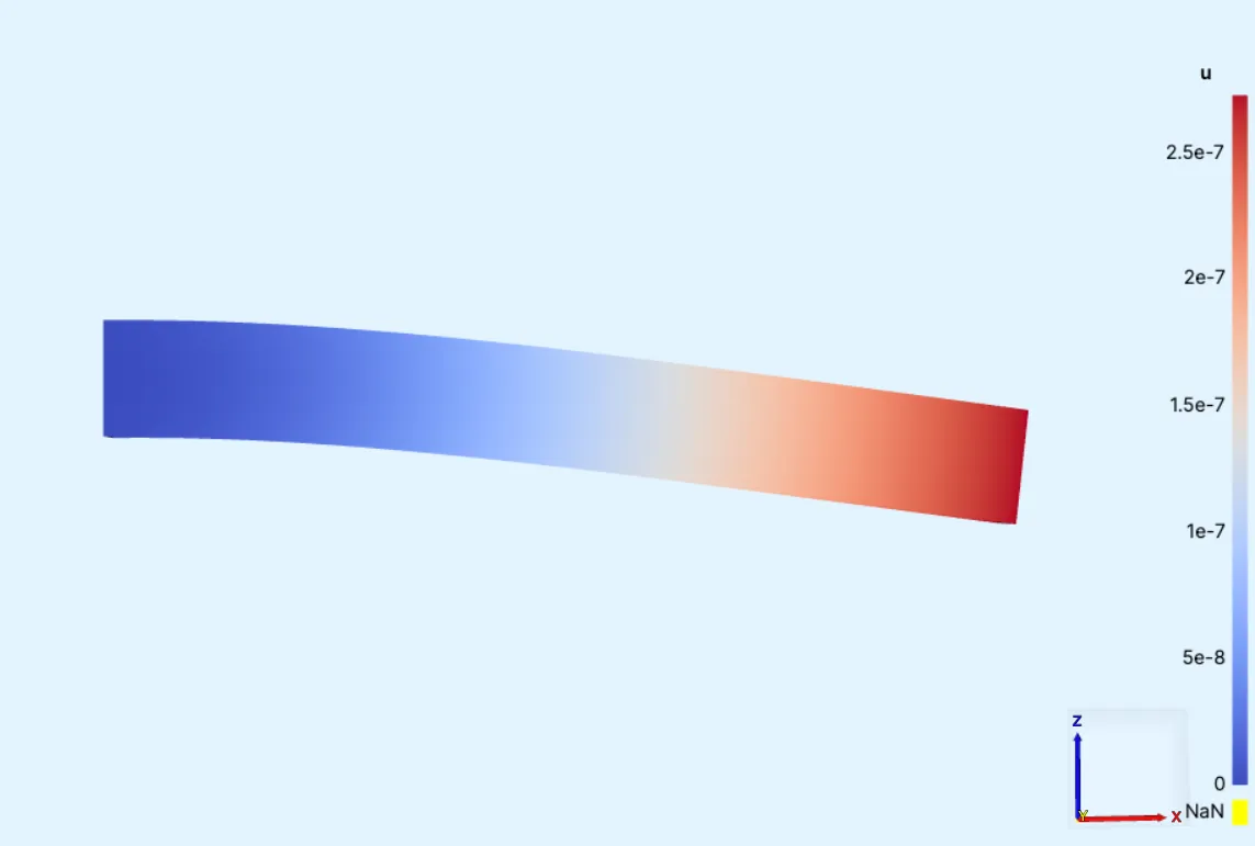
Here, the scale factor is set to
10000.